How to Characterize RF Distortion – Part 1: CCDF Measurements
In today’s wireless systems, frequency spectrum is a finite resource. Complex digital modulation schemes improve spectral efficiency, but they also cause distortions. Characterizing RF devices involves testing unwanted and nonlinear distortion that degrades the modulation quality and interferes with other receivers.
This post, the first in a series, addresses common stimulus-response measurements for RF distortion measurements and how they can help you characterize and troubleshoot your RF designs. Let’s start with evaluating waveform designs and statistical analysis of the signal power levels.
CHaracterize the power in complex wireless signals
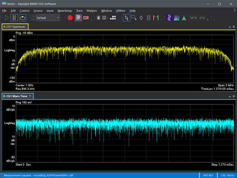
Complex digitally modulated signals have rapid variations in amplitude and phase. The signals appear noise-like in both time and frequency domains and are difficult to quantify because of their random nature and inconsistency. Figure 1 shows the frequency and time domains of a 3GPP HSPA downlink signal. The signal has a fast amplitude variation in both the time and frequency domains.

Evaluate waveform designs with power CCDF staticis
To characterize the signals, you need to extract useful power-related information. Complementary cumulative distribution function (CCDF) power curves characterize the higher-level power of a signal and provide critical information, such as the peak-to-average power ratio (PAPR). CCDF provides a statistic description of the power levels in the digitally modulated signal for evaluating nonlinearities in power amplifiers and transmitters. To learn more about CCDF, refer to my earlier post, “An Essential Step to Generate a Modulation Signal – CCDF.”
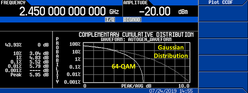
When you simulate a digitally modulated signal with a signal generator, you need to ensure the output signal is not saturated by the signal generator. Figure 2 shows the CCDF curve of a 64-QAM modulation signal at 10 MHz symbol rate.

If the output power of the signal generator is saturated, it impacts not only the output power level accuracy, but also the modulation quality due to gain compression. The amplitude level setting on a signal generator cannot be greater than the maximum output power of the signal generator minus the PAPR value of the simulated signal.
Making a power CCDF measurement
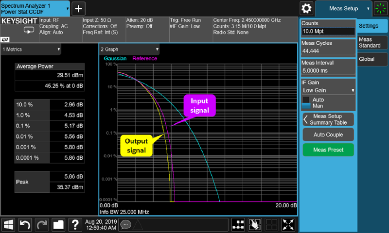
Stimulus-response measurements provide a straightforward method for evaluating the performance of RF devices. When you input a digitally modulated signal to a device under test (DUT), you compare the input and output power CCDF plot with a signal analyzer to see if there is any clipping to the original design. Figure 3 shows a power CCDF plot of an RF power amplifier (PA). The pink trace is the power CCDF plot of the input signal, and the yellow trace is the power CCDF plot of the PA’s output signal. You can see that the output power CCDF plot does not align with the input signal. You need to either reduce the input power level or redesign the PA to minimize the PA’s distortion at the higher output levels.

Conclusion
CCDF curves are an excellent tool to characterize the power distribution of digitally modulated signals. They visualize the effects of complex digital modulation formats and can help you better understand the characterization of your devices under test. You can examine the waveform samples and compare the DUT’s input and output signals with the CCDF measurements.
In the next post, you will learn about RF distortion measurements in the frequency and modulation domains that can help you characterize and troubleshoot your RF designs.