Confronting Measurement Uncertainty in Signal Generation - Part 2: Interpolation Overshoot
It is common to find a gap between ideal conditions and reality. When you generate the desired signal, you need to understand that hardware implementation may cause a certain number of errors to the output signal, and minimize these errors in order to achieve accurate and repeatable measurement results.
In an earlier post, “Measurement Uncertainty in Signal Generation: Waveform Phase Discontinuity”, I discussed the error of phase discontinuity and how to eliminate it. In this post, I will discuss an unexpected error, interpolation overshoot, which results from waveform digital-to-analog conversion (DAC).
What Is Interpolation Overshoot?
A dual arbitrary waveform generator (AWG) provides flexibility when generating modern complex modulation signals. You can simulate your design and create the waveform files on a PC, then use AWGs to convert the digital waveform files into analog signals. During the digital-to-analog conversion, an error message frequently pops up – “DAC Over Range”. Signal overshoots are usually the cause of the problem even if all designed waveform samples are within the DAC range. Let’s take a closer look at the DAC operation and how signal overshoot happens.
Digital-to-Analog Converter (DAC) Input Values
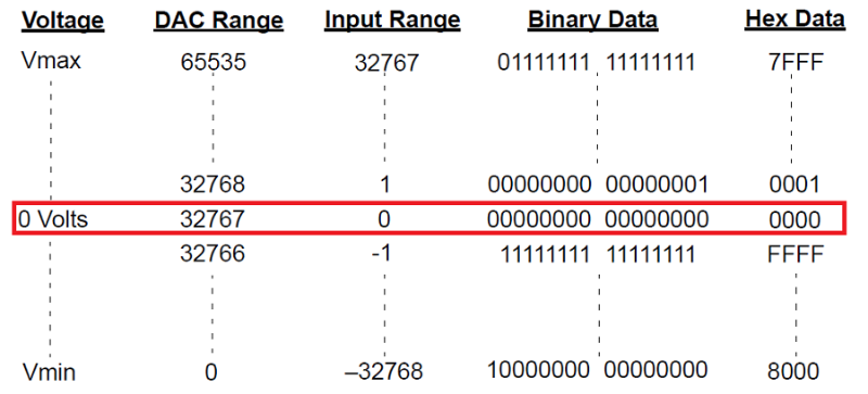
The DAC determines the range of input values for the I and Q data samples. For example, a 16-bit (2 bytes) DAC means that the output range of the DAC splits into 0-65,535 (216) levels. A baseband generator divides the range with positive (32,767) and negative values (-32,768) and accepts binary or hex data formatted as shown in Figure 1.

Figure 1. 16-bit DAC input values correspond to output voltages
DAC Over Range
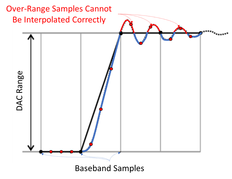
Baseband generators use an interpolation algorithm to resample and reconstruct a waveform that helps reject unwanted sampling images. However, the interpolation can cause overshoots which result in DAC over-range error. For example, the interpolation filters in the DACs can overshoot the baseband waveform. If a baseband waveform has a fast–rising edge, the interpolator filter’s overshoot becomes a component of the interpolated baseband waveform as shown in Figure 2. The red dots are over-sampling points resulting from interpolation processing. This response causes a ripple or ringing effect at the peak of the rising edge. This ripple overshoots the upper limit of the DAC output range (the red curves). The signal generator reports a “DAC Over Range” error, even if all the desired waveform samples (the black dots), are within the DAC range.

Figure 2. The interpolation filters in the DACs overshoot the baseband waveform
How to Eliminate DAC Over-Range Error
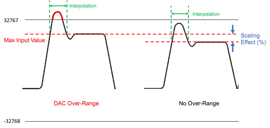
To avoid DAC over-range, you can directly reduce the input values for the DAC, or scale the I and Q input values so that any overshoot remains within the DAC range. Waveform scaling reduces the amplitude of the baseband waveform while maintaining its basic shape and characteristics, such as peak–to–average power ratio (PAPR) as shown in Figure 3.

Figure 3. Waveform scaling to avoid DAC over-range
Note: When you interchange files between signal generator models, ensure that all scaling is adequate for that signal generator’s waveform.
Waveform scaling changes the original waveform design and impacts signal output characteristics.
Dynamic Range
Waveform scaling influences the dynamic range of the signal as shown in Figure 3. When generating signals for out-of-channel measurements such as Adjacent Channel Power Ratio (ACPR) measurements, dynamic range is a key factor for the measurements. You need to find a compromise between dynamic range and distortion performance when playing back waveforms.
To achieve the maximum dynamic range, select the largest scaling value that does not result in a DAC over-range error.
Quantization Errors
Scaling a waveform can create fractional data, lose data, or both. Fractional data
occurs almost every time you reduce or increase the scaling value and causes quantization errors especially when signals are closer to the noise floor. Lose data occurs when either the signal generator rounds fractional data down, or the scaling value is derived using the results from a power of two. For example, scaling a waveform in half causes each waveform sample to lose one bit. These issues cause waveform distortion.
Accelerate the Evaluation with Runtime Waveform Scaling
New vector signal generators, such as the Keysight MXG N5182B and Keysight EXG N5172B provide runtime waveform scaling so that you can evaluate the tradeoff between distortion performance and dynamic range in real-time. This feature does not impact stored data, and you can apply runtime scaling either to a waveform segment or waveform sequence.
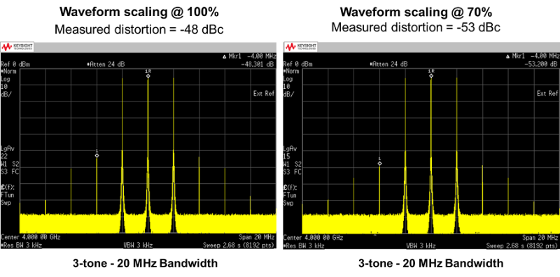
Figure 4 illustrates an example of evaluating distortion performance by adjusting waveform scaling from 100% to 70% on the MXG front panel directly. The scaling reveals a 5-dB improvement in the third order intermodulation distortion (delta of maker 1 and 1R).

Figure 4. Two-tone test stimulus is the result of changing the waveform scaling
Summary
Knowing how your signal generators work will help you understand where errors come from and how to eliminate or minimize them. These errors increase measurement uncertainties and cause inaccurate measurement results. Phase discontinuity and interpolation overshoot occur during digital-to-analog conversion. In my next post, I will discuss how to effectively remove sampling images.
See related posts to learn about Confronting Measurement Uncertainty in Signal Generation: