
How To Control Congestion In Your Data Center
In today's modern data centers, networks are increasingly similar to a highway system and your data as cars. Just like rush hour traffic on the highway, the growth and diversity of applications in today's world result in frequent bottlenecks that slow down network performance. Networks become congested when some connections are overloaded while others sit idle with little traffic, leading to slower application performance and a waste of bandwidth.
In this three-part blog series, we dig a little deeper and look at topics like congestion in the data center, the need for flow control, and standard methodologies deployed to address and notify congestion in switches. We will also review a use case for emulating congestion in SONiC-based switches while observing and contrasting the behavior of a single-ASIC box vs. a Multi-ASIC box.
This first part focuses on the role of a switch in the data center and understanding the flow control and congestion aspects.
Switch transport frames are usually delivered on a best-effort basis with no way of guaranteeing your traffic will reach its destination. When the sending switch sends frames to the receiver switch, you may see a bit error or a full receiver buffer. In the case of a full buffer at the receiver, the switch drops the frame without any notification. Any high-layer protocol or application that requires a reliable delivery method will perform some form of error control and request retransmission. Transport layer protocols, such as TCP, implement some means of the Positive Acknowledgment and Retransmission (PAR) algorithm. This way, reliable end-to-end data communication is possible despite any potential frame loss in the data link layers. Although a PAR protocol will operate correctly in the face of lost frames, you will incur a performance penalty. Depending on the transport protocol, a single lost frame can incur the penalty of idling a data transfer for seconds. Such delays in a data center, where data of magnitude of petabytes must traverse multiple switches, poor performance of latency-sensitive applications is unacceptable.
What is Flow Control?
Flow control is any mechanism that prevents a sender (or senders) of traffic from sending faster than the receiver can receive. Typically, this involves a feedback path from the receiver to the sender, where the sender's transmission rate is throttled based on buffer conditions at the receiver. Ideally, flow control should prevent frame loss due to receiving buffer unavailability and is implemented at the data link layer to accommodate any error control delays in the higher transport or application layers. Think of flow control as a throttling mechanism, where the receiving switch tells the sending switch to slow down the speed at which it is transmitting data. This is similar to the stop lights on freeway entrance ramps. Excessive frame loss can occur due to switching buffer congestion without a protocol that provides flow control. A lack of buffer resources can occur either at an end station or within a switch. In the case of an end station, buffer unavailability is most likely due to a mismatch between the capacity of the receiving station and that of the sending station. In the case of a switch, buffer unavailability may also occur due to output port congestion and the pattern of traffic flowing through the switch. In such a scenario, when a frame fails to deliver to the intended recipient, the data link layer does not indicate the event. To improve performance and reduce latencies, it is essential to give feedback on the frame loss, with mechanisms in place to avoid congestion on the data link layer rather than relying on the transport or application layers. To validate scale and performance and ensure quality in these converged data center Ethernet networks, each new technology must be thoroughly tested in a silo with end-to-end validation as a whole system before deployment.
Keysight’s IxNetwork Data Center Ethernet test solution supports storage area network (SAN) migration to Ethernet, data center consolidation with layer 2 multi-path (L2MP), validation of flow control, verification that switches deployed in data center offer ultra-low latency, and virtualization overlay technologies for server virtualization. The solution enables users to emulate various network components to test converged data center networks from end to end.
What is Priority-based Flow Control?
Priority-based flow control (PFC) is a flow control mechanism at the link level, based on IEEE standard 802.1Qbb. The flow control mechanism works on individual priorities, like IEEE 802.3x Ethernet PAUSE but provides more functionality and flexibility. PFC introduces eight traffic class queues on either side of the link and sends a message with the status of each column across the link, allowing you to control the traffic rate for each queue coming into the receiving station.
PFC working mechanism
PFC can be used for specific traffic in data centers, such as storage. The figure below illustrates an example of a PFC deployment. The eight priority levels that PFC supports help you to prioritize and quickly isolate congestion.
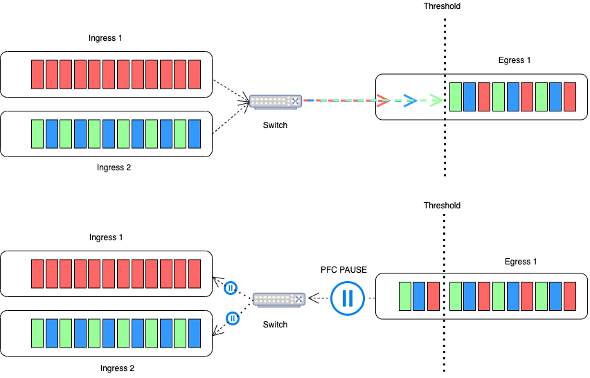
This example shows how PFC can route traffic according to traffic-class-based memory partitions with programmable watermarks. If a particular memory partition starts to fill up and breaches the watermark, a priority flow control message is generated and sent to the transmitting switch, telling it to stop sending frames assigned to that particular traffic class for a specified pause time. Transmission resumes when the pause time expires, ensuring that other non-congested traffic continues to flow. Pause delay times must be long enough so that memory usage levels drop sufficiently before new frames arrive. For example, if jumbo frames are being used or there are long distances between link partners, the watermark setting needs to be lowered, and pause times need to be increased. However, depending on the amount and priority of traffic on a link, pausing traffic can cause head-of-the-line blocking and ingress port congestion, which spreads congestion through the network so PFC alone cannot provide all answers.
Explicit Congestion Notification
Explicit Congestion Notification is an optional TCP feature that allows a router to notify the end host if it is experiencing congestion. The router sends this notification back to the destination host before it starts dropping packets. The ECN-capable host can respond by reducing its transmission rate and congestion on the network to improve overall performance. Illustration below demonstrates how ECN helps to improve the performance of data centers by enabling routers to notify end hosts of network congestion rather than employing an option of pausing traffic to avoid frame loss.
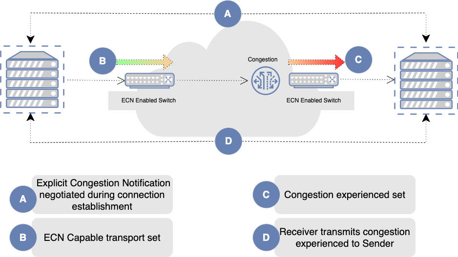
ECN reduces packet loss by forwarding ECN-capable packets during network congestion instead of dropping those packets. (TCP notifies the network about congestion by dropping packets.) During congestion, ECN marks ECN-capable packets that egress from congested queues. When the receiver receives an ECN packet marked as experiencing congestion, the receiver echoes the congestion state back to the sender. The sender then reduces its transmission rate to clear the congestion. The ECN-capable hosts can reduce their transmission rates by using two methods. One method is adapting the window size, and the other is using a lower congestion avoidance threshold. The advantage of ECN is that it deployable on any network and doesn't require any hardware changes, which means you can implement it quickly. Interestingly, some streaming video services use ECN to help reduce latency and therefore reduce buffering time. They use ECN because it's a low-cost way to implement a better user experience with as low latency as possible.
Data Center Quantized Congestion Notification (DCQCN)
Data Center Quantized Congestion Notification (DCQCN) is a solution that combines both ECN and PFC, as discussed earlier. ECN helps overcome the limitations of PFC to achieve lossless Ethernet. The idea behind DCQCN is essentially to allow ECN to do flow control by decreasing the transmission rate when congestion starts, thereby minimizing the time PFC is triggered, which stops the flow for a single priority class. By accurate timing, we can ensure that PFC does not trigger too early or too late and can help balance the operation of DCQCN to eliminate end-to-end congestion. DCQCN relies on explicit congestion marking by switches using the ECN bits in the IP header. Switches detect congestion by monitoring queue sizes. When a queue size crosses a configured threshold, switches start randomly marking packets, indicating they are crossing a congestion point as illustrated below.
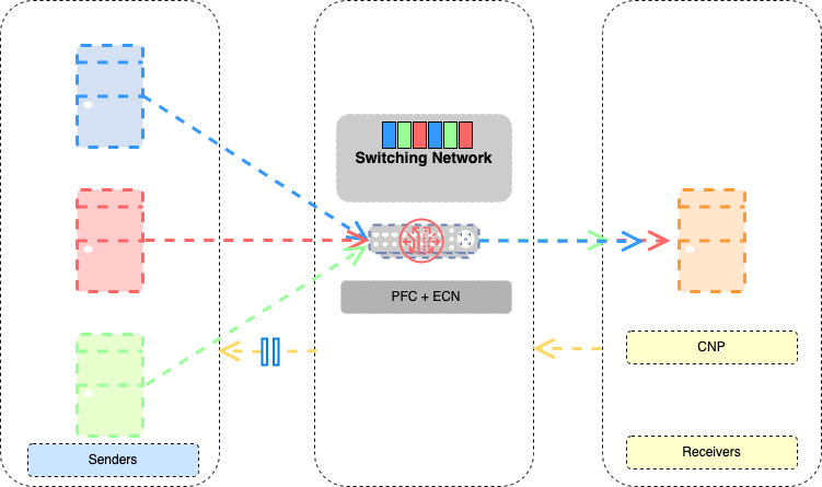
When a destination node receives marked packets, it processes them and sends an explicit congestion notification packet (CNP) to the source. The reception of the CNP results in a reduction in the injection rate of the corresponding flow, using a specified algorithm with configurable parameters. DCQCN is a mechanism to control traffic in congestion spots. Unfortunately, tuning the parameters is tricky, so you must perform much testing to find an appropriate setting that provides optimal performance. But as networks become increasingly complex, so do the challenges of ensuring peak network performance and resiliency. Forget about simply testing for sluggish response times—the proper testing tool must now assess complex network topologies with thousands of network devices, emulate sophisticated traffic flows, and conduct stress tests under countless scenarios and network conditions.
Keysight’s IxNetwork delivers performance testing under the most challenging conditions. Capable of generating multiple terabytes of data and analyzing up to 4 million traffic flows simultaneously, IxNetwork scales to handle the most powerful devices and the most extensive networks.
Stay tuned for our next blog post where we will review RDMA technology and how PFC, ECN, and DCQCN contribute to controlling congestion in RDMA deployments.