
EM Simulation Technology and When to Use It
High frequency system design is hard. If you’ve ever tried it, you know what I’m talking about. High frequency systems are complex, and they are becoming more and more common. This means your challenging design job just got even tougher. Perhaps one of the most difficult challenges you face is accurately modeling large portions of high-frequency systems. Electromagnetic (EM) simulation is certainly up to the task, but with more than one method to choose from, how do you even know where to begin?
The good news is that while there is no one ideal method for every scenario, the most established options tend to line up well with the application areas in which they will be used. Let’s take a closer look.
Method of Moments (MoM)
Among all techniques used to solve EM problems, the method of moments (MoM) is one of the hardest to implement. It is a numerical computational method that transforms Maxwell’s equations into integral equations which, when discretized, yield a coupling matrix equation of the structure.
The advantage of MoM is that it only requires calculation of boundary values, rather than all values throughout the problem space. That makes it significantly more efficient for problems with a small surface/volume ratio and well suited for simulating very complex structures.
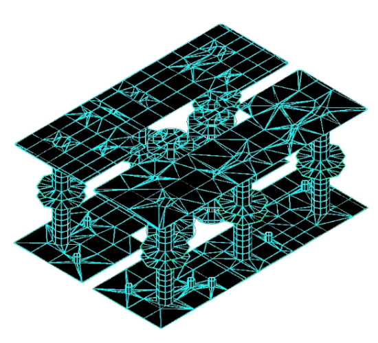
MoM discretization of a 3D planar structure (PCB differential via stubs)
Finite Element Method (FEM)
Based on volumetric meshing, the FEM technique divides the problem space into thousands of smaller regions and represents the field in each sub-region (element) with a local function. The resulting model is then divided into multiple tetrahedra, referred to as the finite element mesh.
Design engineers often use FEM in circuit design applications, such as for transition designs and interconnect analysis. The FEM solver can handle arbitrary shaped structures like bond wires, conical shape vias, and solder bumps where z-dimensional changes appear in the structure. FEM solvers can also simulate dielectric bricks or finite-size substrates. And as an added benefit, integrating an FEM field solver into the circuit design environment reduces the total time required for entering the design geometry through to final EM simulation results.
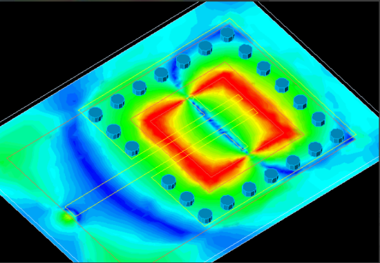
FEM simulation of a SIW cavity-backed patch antenna
Finite Difference Time Domain (FDTD)
Finite difference time domain (FDTD) algorithms solve Maxwell’s equations in an explicit way. The FDTD method utilizes a mesh built from rectangular or Yee cells in which field values are updated, time-step by time-step, as electromagnetic waves propagate through a structure. With this approach, a single FDTD simulation can provide data over an ultra-wide frequency range.
Because of its simple, robust nature and ability to incorporate a broad range of nonlinear materials and devices, FDTD is often used to study a wide range of applications, including antenna design, microwave circuits, bio/EM effects, and photonics. Recent advances in computer speed and memory capacity have made FDTD solvers increasingly popular with designers. This approach is particularly well suited for wireless design.
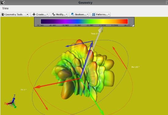
Radiation pattern of 8x16 patch array designed and simulated using the PathWave EMPro FDTD Simulator
Conclusion
As ICs become more complex, EM circuit simulation is even more critical to designing powerful and efficient devices. You can avoid a lot of the challenges that come with EM simulation just by using the right simulator for your application. While MoM has specific advantages for planar structures, FDTD is better to solve geometrically complex 3D structures.
When using the right EM simulator, you can accurately model large portions of the system or the entire system itself. Knowing which EM simulator to use will help you when you begin your next high-frequency circuit design.