
Generate and Analyze Custom Modulation Schemes
Satellites enable high data rate communications for emerging applications like connected cars and 5G. Engineers employ complex modulation schemes to improve spectral efficiency and minimize nonlinear amplification in the RF power amplifier. In an earlier post, we discussed that amplitude and phase-shift keying (APSK) improves nonlinear distortion for satellite communications; orthogonal frequency-division multiplexing (OFDM) increases spectral efficiency for high-throughput satellite communications. However, both modulation techniques bring in test challenges — generating and analyzing custom, proprietary modulation schemes. Engineers spend a lot of time to simulate and analyze the custom modulated signals. In this post, we will explore how to generate and analyze custom modulation schemes with flexible software tools that help you reduce time spent on signal simulation and analysis.
Generate Custom Modulation Signals
RF vector signal generators offer two flexible baseband architectures with complementary features for generating complex digital modulation signals, real-time and arbitrary waveform generation. Engineers often build their own I/Q constellation waveform with the arbitrary waveform generation mode using software tools, such as Matlab, Keysight PathWave SystemVue, or PathWave Signal Generation software.
Learn More: "Real-Time and Arbitrary Waveform Generation Mode: Which One is Right for Your Test?"
Define custom modulation constellation
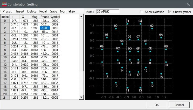
Figure 1 illustrates the PathWave Signal Generation constellation editor tool for generating a 32APSK modulated signal. The custom signal-creation tool allows a user to enter the desired I and Q values (corresponding magnitude and phase) and symbol data that corresponds to each point on the constellation diagram.
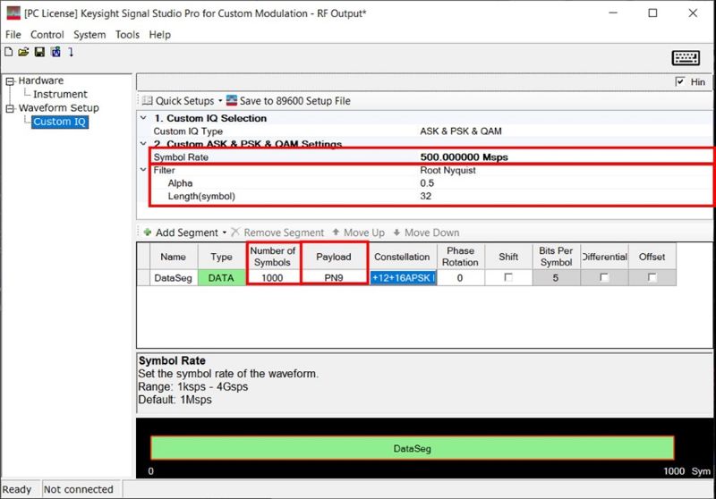
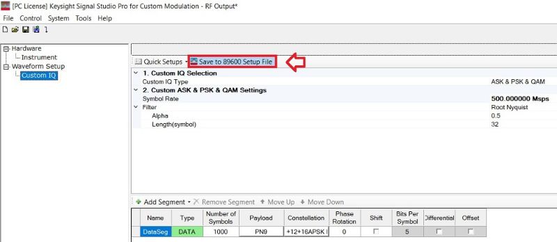
Once you completed the constellation edits, you can set modulation parameters, such as waveform length (number of symbols), payload data, symbol rate, and baseband filter as shown in Figure 2 to generate the waveform file. Of course, you need to understand baseband waveform data and structure for vector signal generators if you are using your own software tools.
Apply custom FIR filter
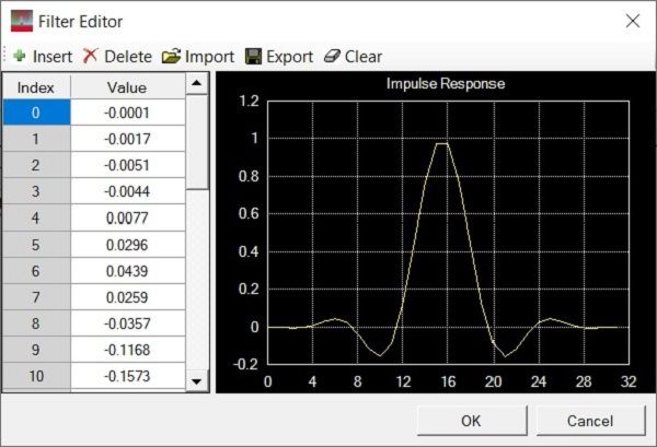
The waveform generation software tool also offers a baseband filter editor to edit, import, or export the filter coefficients as shown in Figure 3 and applies the finite impulse response (FIR) filter to the designed modulation schemes. The software enables you to create and customize waveforms to characterize the power and modulation performance of your components and transmitters. Easily manipulate a variety of signal parameters to simplify signal creation.
Analyze Custom Modulation Schemes
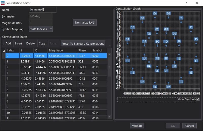
To make a custom IQ demodulation analysis, you need to define the IQ location of the constellation state. Figure 4 shows the constellation editor of Keysight’s PathWave Vector Signal Analysis software, Like we did for the signal generation, you need to configure the IQ values for each symbol. Also, setup the relevant modulation parameters, such as symbol rate and baseband filter in order to demodulate the signal correctly.
Accelerate demodulation analysis with setup files
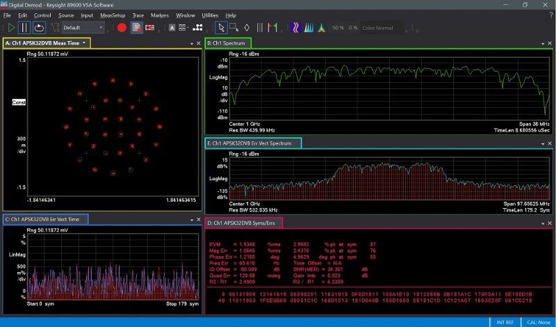
The waveform generation software tool also lets you save setup files for configuring signal analysis measurement applications as shown in Figure 5. That way, you just recall the setup file and do not need to edit the constellation map and set up all the modulation parameters in the signal analysis tool again. Figure 6 shows the demodulation analysis of the 32APSK signal using a signal analyzer with ease.
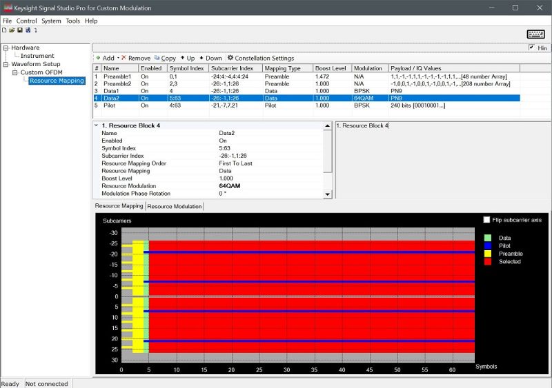
Generate and analyze custom OFDM signals
Likewise, creating and analyzing custom OFDM waveforms requires a deeper background in OFDM technology. Fortunately, a custom signal-creation tool can accelerate the waveform generation and analysis of standard or proprietary OFDM signals. Figure 7 illustrates a custom OFDM setup for resource mapping, including subcarriers (frequency) and symbols (time), using a custom signal-creation tool. The signal analysis application can load the setup files in the creation tool and demodulate the signal with ease.
Summary
Most communications systems optimize efficiencies in system designs, including spectral, power, and cost. Engineers employ different modulation techniques to improve spectral efficiency and minimize nonlinear distortion in the system. Often, customized modulation schemes are used to address specific communication channel issues, hardware limitations, and data throughput requirements. Generating and analyzing modulated signals for modern satellite communications brings challenges, as the signals are customized proprietary modulation schemes.
Keysight offers a flexible custom modulation generation and analysis software tools. These software tools help you reduce time spent on signal simulation and provides a setup file for configuring your signal analyzer for demodulation analysis.