
Remove Frequency Responses for 5G NR Signal Analysis
Industries from wireless to satellite communications require wider analysis bandwidth at higher frequencies to meet demands for higher data throughput. 5G New Radio (NR) operates in two frequency ranges (FR): FR1 for sub-6 GHz frequencies and FR2 for millimeter-wave (mmWave) frequencies. Maximum channel bandwidth increases to 100 MHz for FR1 and 400 MHz for FR2. The higher frequencies and wider bandwidths for 5G NR bring in new design and test challenges. One of the major challenges is frequency responses. In this post, I will discuss how to correct frequency responses for signal analysis.
Frequency Responses
The poor frequency responses could be either from the DUT, the test system, or them both.
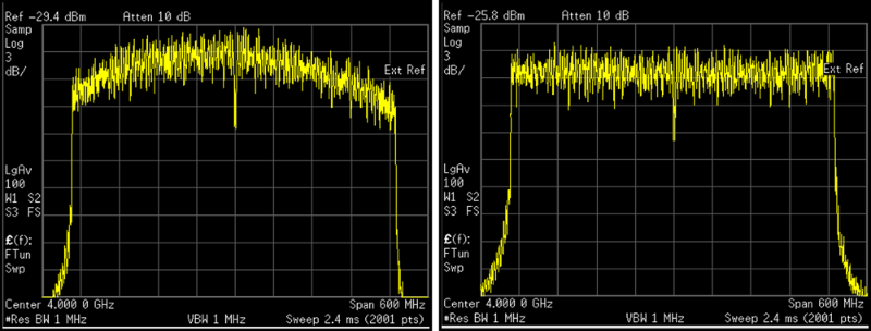
A signal analyzer internal circuitry, including mixers, the filter, and amplifiers, contribute frequency responses that degrade modulation quality. The responses occur at different frequencies, affecting phase and amplitude. A signal analyzer provides an internal calibration routine to correct its frequency responses, including amplitude and phase responses. Figure 1 illustrates an OFDM signal with poor frequency responses (the left figure) and flat frequency responses (the right figure). The poor responses could be either from the DUT, the test system, or them both.
Correct Frequency Responses for External Test Network
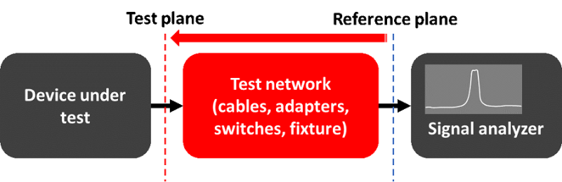
When you are building a test system, cables, connectors, switches, and fixtures in the paths between the signal analyzer and the device under test (DUT) can degrade measurement accuracy because of flatness errors. The frequency responses get worse when you test 5G NR FR2 signals with wider bandwidths and higher frequencies. You need to extend the measurement accuracy from the signal analyzer’s input port (reference plane) to the DUT’s test port (test plane), as shown in Figure 2.
Using a signal generator and power sensor for amplitude corrections
Signal analyzers allow you to configure amplitude corrections and complex corrections, which include both amplitude and phase corrections, to correct frequency responses. For amplitude corrections, you can measure the amplitude frequency responses of the test network using a signal generator plus a power meter and sensor, then input the correction values to the signal analyzer.
Use a vector network analyzer for complex corrections
For complex corrections, you can make frequency response measurements of the test network using a vector network analyzer and save the measurement results in the .s2p format. Keysight X-Series Signal Analyzers allow you to load the .s2p file and correct amplitude and phase frequency responses.
Use a comb generator for complex corrections
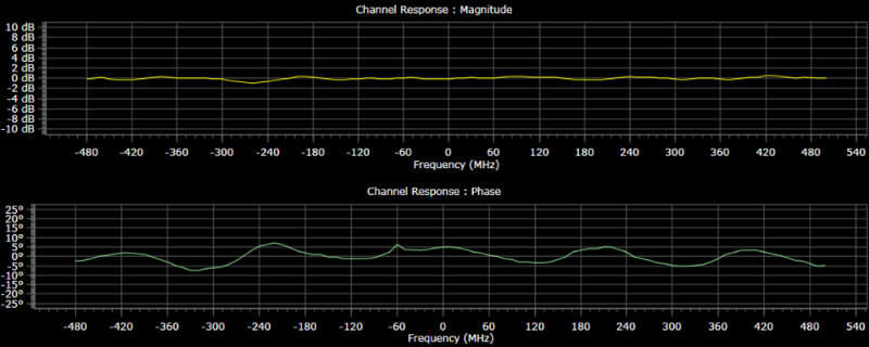
Another calibration tactic is using a comb generator. The comb generator is a universal receiver system calibrator which is easily injected at the desired calibration plane (the input of the test network). It generates CW tones of known amplitude and phase. A signal analyzer measures the amplitude and phase of each tone at the output of the test network and compares them to the known amplitude and phase. Figure 3 shows a channel response of magnitudes and phases of a test network.
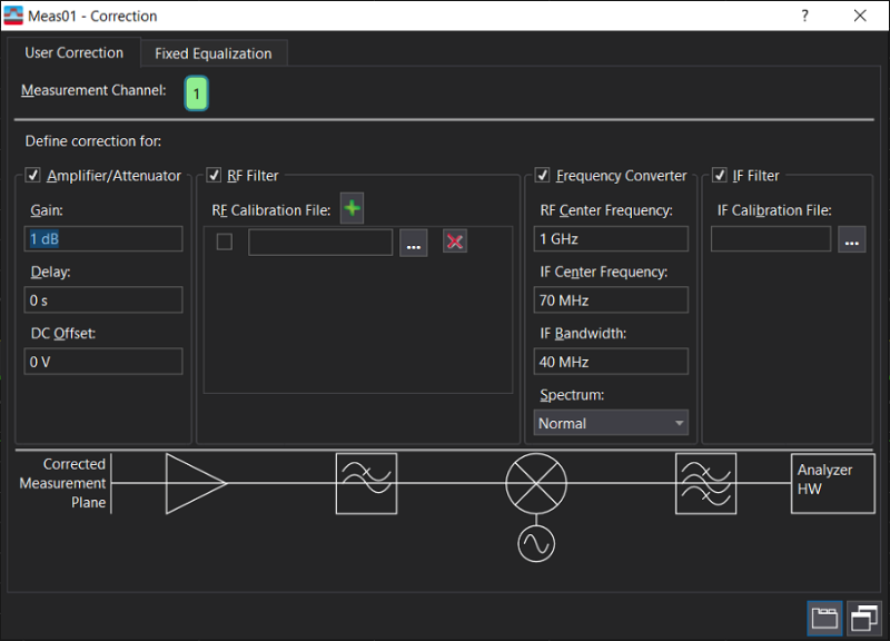
Keysight PathWave vector signal analysis (VSA) software allows a user to control corrections to compensate for external devices connected to the signal analyzer, including attenuators, amplifiers, radio-frequency (RF) filters, mixers, and IF filters, as shown in Figure 4.
Make Rapid, Accurate and Repeatable Measurements
Developing a reliable test system with optimum performance is essential but calibrating the RF channel is a challenge. The channel frequency responses get worse when you test 5G NR FR2 signals with wider bandwidths and higher frequencies.
You need a test and measurement solution that addresses the signal analysis needs for a diverse set of wireless devices and systems, and provides the performance required to make rapid, accurate and repeatable measurements across both RF and mmWave frequencies. Keysight’s new MXA X-Series Signal Analyzer enables you to overcome the challenges in identifying signals at higher frequencies and offers wider bandwidth to meet a breadth of wireless application test requirements.
To learn more about analyzing 5G NR signals, download white paper Four Tips for 5G New Radio Signal Analysis.