
3 Tactics for Building Microwave Wideband Signal Generators
Strong demand for faster data rate applications has triggered the need for new technologies capable of wide signal bandwidth. Cellular communication is transitioning from 4G to 5G to enable extreme data throughputs; satellite communication providers are building networks in space to enable high-speed communications from anywhere; and Wi-Fi stakeholders are embracing the new 6 GHz band to increase peak throughput via 1.2 GHz of accessible and unlicensed spectrum.
While increasing signal bandwidth offers a great way to achieve faster data rates, it also introduces a new challenge: the need to meet signal quality requirements at higher frequency ranges, such as frequency responses across the entire bandwidth, and I/Q modulator imperfection. Here are three common tactics for building wideband signal generators at high frequencies.
Tactic 1: Modulate Wideband I/Q Signals
Use a wideband arbitrary waveform generator (AWG) to generate baseband I and Q signals that are fed into an I/Q modulator in a vector signal generator (VSG) as shown in Figure 1. With this architecture, you can use off-the-shelf instruments to build the system, but need to calibrate the frequency responses across the entire bandwidths of both the AWG and VSG. These responses occur at different frequencies and output levels and include both amplitude and phase response. In addition, you need to minimize the modulator’s impairments that include carrier feedthrough and I/Q mismatch errors.

Tactic 2: Upconvert Wideband Intermediate Frequency (IF) Signals
There are two different approaches to generate wideband signals using intermediate frequency (IF) up-conversion. Generate the IF signal using a calibrated RF VSG or a wideband AWG. Then, feed the IF signal to a mixer to upconvert the signal to the desired microwave or millimeter-wave frequencies as shown in Figure 2 and Figure 3. Likewise, you need to calibrate frequency responses across the entire bandwidths at the selected frequencies and power levels. The upconverter typically does not have band filters to remove the images. So, when you generate a wideband signal at the selected frequency using the IF up-conversion method, you need to know where the image signal is located and whether the image will impact your measurements.


Calibrated RF VSG
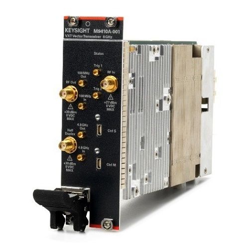
A calibrated RF VSG, such as vector transceiver (VXT) M9410A, covers up to 6 GHz frequency ranges for the most commercial standard frequency bands with up to 1.2 GHz signal generation bandwidth. In addition, it also integrates a vector signal analyzer (VSA) with the same frequency range and bandwidth for signal analysis. Figure 4 shows VXT M9410A that integrates a 6-GHz VSG and a VSA in a 2-slot PXIe module with up to 1.2 GHz bandwidth.
Wideband AWG
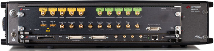
The wideband AWG has less I/Q modulation and fewer up-conversion errors as they are carried out as a mathematical operation by a digital signal processor. However, the DAC requires a higher sampling rate in order to cover the entire IF signal. The M8190A AWG as shown in Figure 5 is the source of greater fidelity, delivering high-resolution 14-bits and wide bandwidth up to 8 GSa/s – simultaneously, or 12-bits resolution up to 12 GSa/s.
Tactic 3: Fully Calibrated Wideband VSG
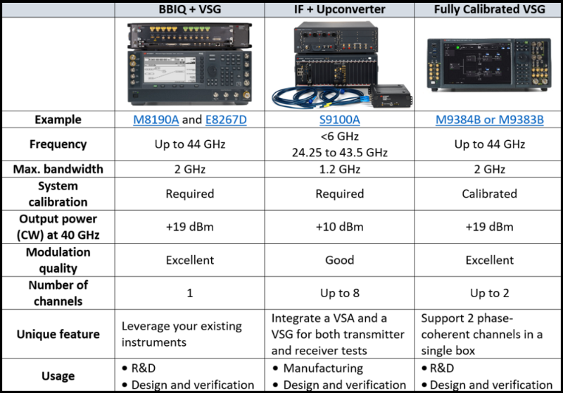
A fully calibrated wideband VSG has integrated a wideband baseband generator, an I/Q modulator, and an output section in a box and has corrected frequency responses at different frequencies and output levels. Figure 6 illustrates a fully integrated and calibrated VSG. For example, a fully calibrated microwave VSG provides < ± 0.9 dB RF amplitude flatness across the entire 2 GHz bandwidth with factory channel corrections. Table 1 shows a comparison table of the different solutions for wideband signal generation.

Summary
The sharp increase in network traffic due to rapidly evolving wireless communications systems has created a strong demand for more bandwidth to support next-generation wireless standards and technologies. You can choose off-the-shelf instruments to build solutions, or integrated solutions for wideband signal applications, such as characterizing RF components, system design and verification, and manufacturing.
In my next post on this topic, you will learn about the impacts of frequency responses and how to correct the responses of your test system.