
The ABCs of Analog Demodulation
If you’re an RF engineer, you’ll know that demodulation is the process of extracting the original information-bearing signal that was imposed on a carrier wave.
But, why would you want to impose a signal on a carrier wave, or rather modulate an analog signal, in the first place? Additionally, what does the exact process of analog modulation of a signal and then its demodulation in a radio link look like?
Analog Modulation
Why We Do It
So, why do we modulate an analog signal to begin with?
Well, for one, audio signals do not have the right propagation properties to be transmitted over a substantial distance and reach a receiver that may be far away. Audio signals may also have trouble penetrating obstacles (trees, clouds, windows, etc.) that may get in the way en route to their destination. This means that you may find it challenging to transmit data as is in an audio signal.
However, radio frequency (RF) signals have propagation characteristics that enable you to transmit signals over great distances, or through objects, and can reach your receiver just fine.
Therefore, to overcome the limitations of audio signals, you may use analog modulation to combine your audio data with an RF carrier which can then be transmitted over huge distances and through obstacles to your receiver. By doing so, your audio signal can get to your receiver without an issue.
What Is Modulation
The word modulate means to exert a modifying force upon. What we mean by that is to exert the influence of an audio signal, which can be a continuous waveform of voice, music, data, or test tones, and then inject that into a modulator which modifies, or imposes, a change on an RF carrier — the product of the two being a modulated signal. You can see this below in step 1 of Figure 1.
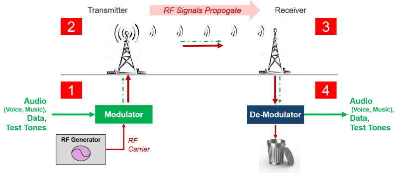
Figure 1. The 4 major steps taken for modulating an RF Signal on a radio link & then demodulating it at the receiver
On a radio link, the modulated signal then passes to a transmitter, step 2 of Figure 1, and propagates over a space to some distant receiver, step 3 of Figure 1. This modulated signal is then de-modulated and the user on the other side can receive the audio content, step 4 of Figure 1. The RF signal is then thrown away at that point.
Recap
The reason why we go through all these steps (1 – 4) is because the properties of the RF signal in this link are very valuable. The first of which we already mentioned – RF signals enable audio signals to travel large distances and through objects. The second is that RF signals can be more easily channelized, or frequency multiplexed. This means that you can set aside frequencies such that thousands of transmitters can simultaneously emit energy into the airwaves and go back and forth across the same receiving antenna simultaneously. Thanks to channelization, the receiver can tune to one of the frequencies it wants to listen to and reject all the others. This makes the airwaves easier to use by many different purposes or devices at the same time.
So, to review, modulation is the act of translating a low-frequency or baseband signal (voice, music, and data) to a higher frequency. This signal modulation is done for two reasons primarily:
- To allow the simultaneous transmission of two or more baseband signals by translating them to different frequencies
- And to take advantage of the greater efficiency and smaller size of higher-frequency antennae
In contrast, a demodulator separates the two components, so you can recoup the valuable information you had sent and dispose of the RF signal used to carry the information.
Analog Demodulation
If you are working with analog modulated signals, it’s in your best interest to test that the modulation has been done correctly and that your signal is linear, bears low distortion, and ultimately is received and demodulated by your receiver properly.
To do this, there are a variety of tests you may need to perform and set up, including:
- Transmitter tests
- Signal generator tests
- Component tests
Transmitter Tests
For testing the analog modulation of a transmitter, connect the transmitter output to the input of the signal analyzer. The analyzer will look at the RF signal, plus the modulated audio content. An analog demodulation application on your signal analyzer would make it easier to look at the details of both the signal modulation and demodulation.
One note is that analog demodulation is not only essential in testing FM or AM transmitters, but is also a powerful troubleshooting tool for analyzing unintentional signals from digitally modulated transmitters such as 4G/5G cellular phones, and wireless LAN and WiMAX devices.
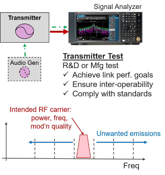
Figure 2. Transmitter test use-case and what it is validating in your radio link
Signal Generator Tests
If you work in a calibration lab, you may need to test a signal generator for annual calibrations. The signal generator shown below can be used for the design or manufacturing of a receiver in a radio link. The generator usually has a modulator inside of it and an audio section. If you ever wanted to verify the signal coming out of your signal generator is correct, you can use a signal analyzer to verify it and do a complete calibration of the signal generator.
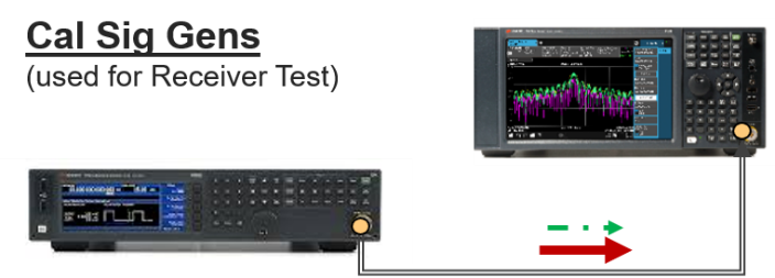
Figure 3. Example setup of a signal analyzer used to calibrate a signal generator
Component Tests
You may need to test individual components, such as a modulator or amplifier. In the case of a modulator, you will stimulate one input with an audio generator and the other input with an RF signal generator. Connect the output to the signal analyzer. Then the analyzer will show you the characteristics of the modulator. This test works for phase or amplitude modulators.
In the case of an amplifier test, you would stimulate the amplifier with a modulator to look for distortion or compression problems using an analog demodulation application with the signal analyzer.
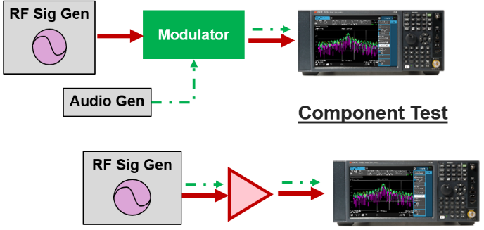
Figure 4. Example setup of a signal analyzer used to test components
How to Make Demodulation Measurements
The best way to characterize whether your signal has been modulated appropriately is by using a signal analyzer equipped with an analog demodulation app. While you can use a measurement instrument’s standard swept-span view, you may have difficulty identifying the characteristics of the modulated signal.
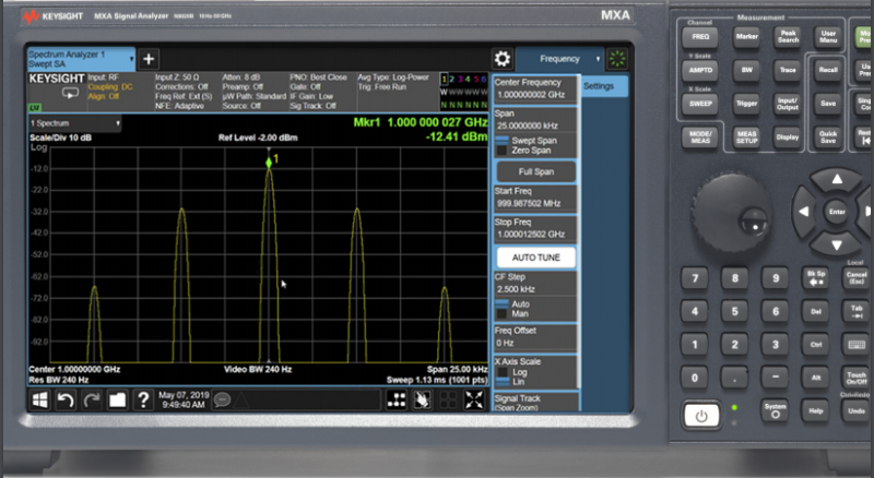
Figure 5. A modulated signal in swept-spectrum view
Looking at Figure 5 above gives you a good view of how difficult it might be to identify your signal’s behavior. This is a frequency modulated (FM) signal, but we would like to have more data about the signal beyond what is already displayed here.
Signal analyzers with analog demodulation apps help us acquire useful data on modulated signals that you wouldn’t see otherwise. Instead of trying to play with the analyzer’s settings, displays, and measurements, you can immediately gain a wealth of information about your modulated signal using a simple app.
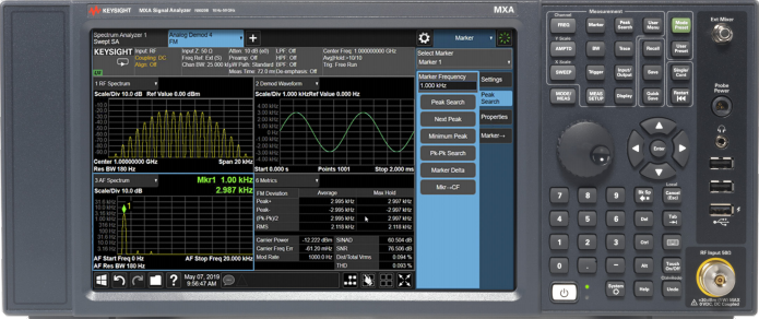
Figure 6. FM Signal measured with Keysight’s N9063EM0E Analog Demodulation App
The Keysight analog demodulation application has a quad view that displays the RF spectrum, demodulated waveform, the spectrum of the audio signal after demodulation, and the metrics of the modulation and distortion.
In this view, you can immediately see the characteristics of your FM signal … and similar measurements can also be made across AM, PM, or FM Stereo modulation types.
The RF spectrum view presents the modulated signal along with results of demodulation, where we see the modulated carrier signal power in the frequency domain.
In the demodulated waveform view, the measurement retrieves the baseband signal from the modulated signal via the demodulation process and displays the baseband signal in a pattern of modulation depth/deviation versus time.
In the spectrum of the audio signal after demodulation, by applying the fast Fourier transform to the baseband waveform, the AF spectrum demonstrates the baseband signal behaviors in the frequency domain graphically.
Finally, he modulation metrics view gives us the numeric result that demonstrates the modulation parameters and error information.
Looking at Figure 6’s display above, an FM signal is shown with the quad view. This analysis provides you with insight into the performance of your device, and the quality of the signal, as a modulated signal and post demodulation.
Conclusion
An analog demodulation application can help you analyze your modulated, transmitted signal and even take the two components back apart (demodulation). This way you can recover valuable information and measure the quality of your modulation and transmission.
Analog demodulation application measurements help you:
- Monitor the RF spectrum
- Demodulate your waveform
- Evaluate your modulation metrics
- Apply post-demodulation filters
- Analyze transient signals
- Analyze FM stereo and RDS signals
Being able to easily access this information will improve design, evaluation, and manufacturing of your analog devices. Doing so has never been easier using a signal analyzer equipped with analog demodulation software.
For more information on how a signal analyzer with a built-in analog demodulation app can help with your testing, check out the following resources: