What is Flatness Correction And Why it Matters
Written by Tit Bin Teo, Technical Engineering Manager
What is Flatness Correction?
You are probably all too familiar with issues caused by long connections. The longer the cable, the higher the loss. For power supplies, we have remote sensing to compensate for cable loss. For signal generators, we have flatness correction. Unlike direct current (DC), RF transmission loss varies with frequency. In RF, we refer to this behavior as the frequency response. Many signal generators allow us to compensate for this transmission loss with flatness correction. Flatness correction ensures that we continue to have flat output power even after our signal has passed through all the cables, switches and splitters.
Why Care Bother with Flatness Correction?
Flatness is one of the important specifications of RF power amplifiers. To test for flatness performance, we need to ensure our test system has better flatness performance than our device under test (DUT). Unfortunately, all the cables and switches used in your test system have their own typical frequency responses and they degrade the overall flatness performance of your test system. Use flatness correction to achieve robust flatness performance at the input to your DUT.
Performing the Flatness Correction
Many signal generators allow you to digitally adjust the output amplitude at specific frequencies. Advance signal generators let you adjust up to 1601 frequencies that are either sequentially or arbitrarily spaced. These advance signal generators use a table of power level corrections to compensate for external cable and switch losses. If your power meter and power sensor are compatible with your signal generator, the power level correction table can be generated automatically. Of course, you can always perform flatness correction manually.
Manual Flatness Correction
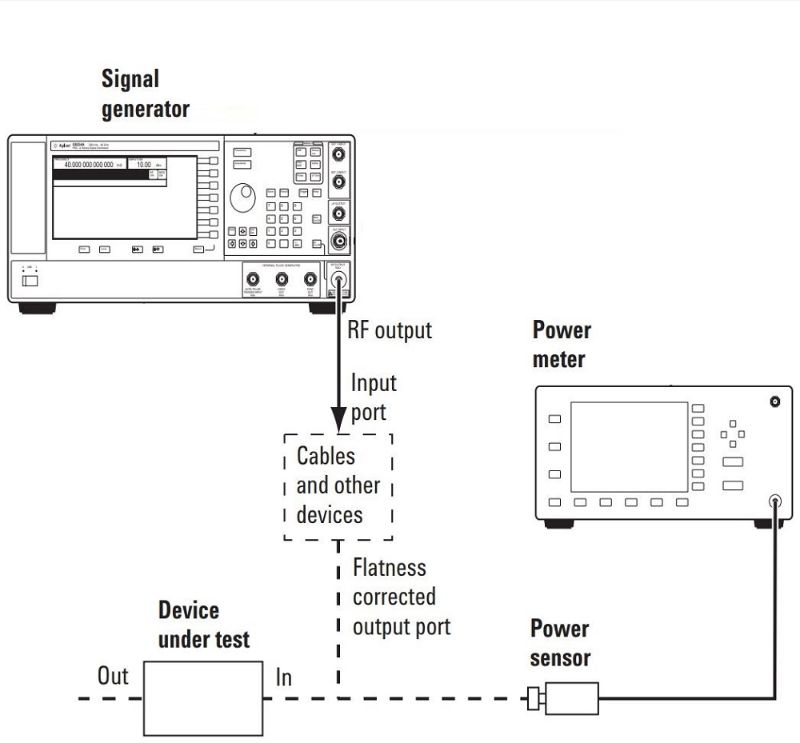
To perform the flatness correction manually, you will need to get a power sensor with a power meter. Make sure the power sensor’s calibration factors are already loaded into the power meter. Make the connections as shown in Figure 1 below.

Figure 1. Manual flatness correction setup
To begin, set the signal generator to output 0 dBm. Next, open the User Flatness Table Editor. Key in the difference between the power meter reading and the output from the signal generator, which in this case is 0 dBm. You may have to tweak the difference that you keyed into the User Flatness Table until you get a 0 dBm reading from the power meter. Repeat this step until you covered all the frequency points. Now you have a completed user flatness array. Remember to save this array into your signal generator. You can access the detailed steps from the MXG signal generator’s user guide.
Automatic Flatness Correction
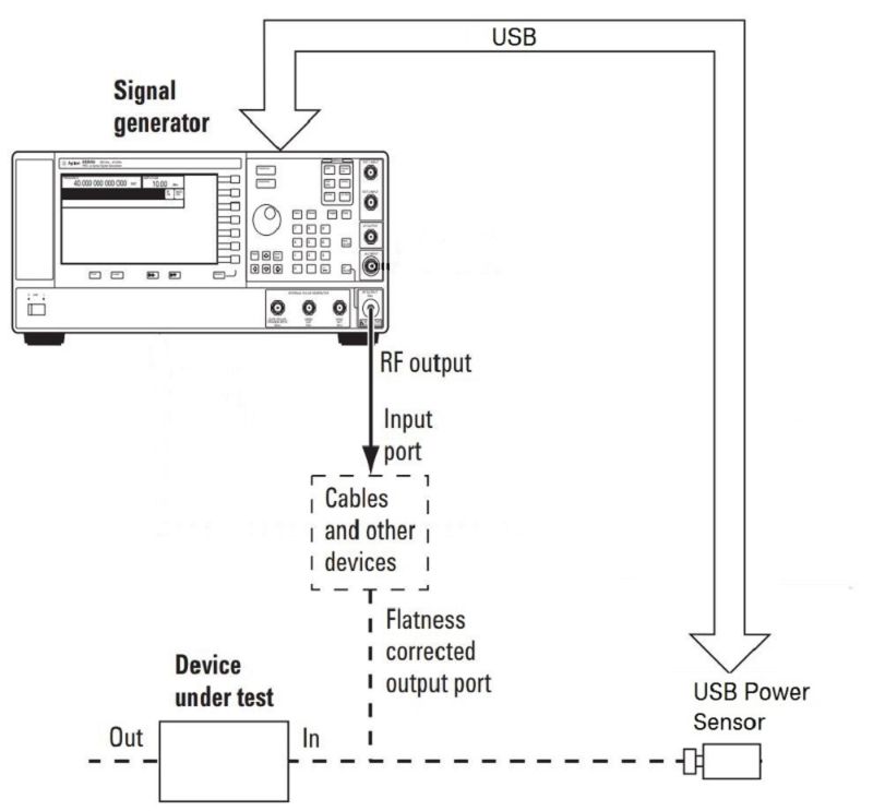
Figure 2 shows the automatic flatness correction setup using the Keysight MXG N5182B signal generator. This signal generator works with the U2000A series USB power sensor to automatically generate the table of power level corrections.

Figure 2. Automatic flatness correction setup
Be sure to connect the power sensor to the connector that will connect to your DUT. This is the point where we want to achieve flattest possible output.
Start by creating a table of power level corrections (also called user flatness array). To do this, configure both the USB power sensor and the signal generator, and connect them as shown in Figure 2 above. The N5182B’s user guide details how the configuration is implemented for both the power sensor and the signal generator.
During the correction value creation process, you will need to set the signal generator to output 0 dBm. The signal generator will then read the power level from the power sensor, calculate the correction values, and store the correction values in the user flatness array. This array is created automatically as the signal generator sweeps across your frequency span. Once the user flatness array is created, you will want to save this array into your signal generator’s memory. To use this flatness array, just enable the flatness correction feature in your signal generator and select the specific flatness array.
Learn More
Flatness correction is used to compensate for transmission loss due to cable and switch impedance. However, you can also use this approach to improve flatness even if you have amplifiers and filters along with your signal path. Many signal generators come with flatness correction. Take advantage of this feature and remove doubt from your test results at no additional cost.
And take advantage of our new whitepaper to build a solid foundation for your signal generator knowledge. Download “The Essential Signal Generator Guide” and start learning about signal generators today.
Explore key signal generator specifications and why they are critical to your measurement applications, check out the free course: The ABCs of Signal Generators.