
What is Power Integrity and How Do I Measure It?
What is power integrity?
If you’re a digital developer, or an analog signal chain engineer, you might be wondering why you need to know anything about power. Power is just the rails that you need to connect to your IC to get it going. Slap a DC/DC converter between the battery or the wall socket and you’re good to go, right? Not quite.
It’s important to remember that your circuit boards are swarming with layers of traces and vias carrying alternating signals at various frequencies, from high-speed digital protocols to transient ripples on what should be a flat, DC power rail. Alternating signals can affect each other in unwanted ways.
Power integrity is the practice of ensuring that the ripple on your power rails is not affecting the signal integrity of other parts of the system. Let’s talk a little about what you can do to measure your system’s power integrity.
What causes issues with power integrity?
Switched mode power supplies can create current transients when converting from an AC source to a DC rail. Transients react with inductance in the channel to create voltage ripple noise, a main source of power integrity issues. Since every component is connected to the main power supply, ripple noise can transfer to any part of the system via crosstalk.
Another source of power integrity issues is electromagnetic interference (EMI). Both power and analog traces can be affected by each other’s EMI. A common source of EMI is an unfiltered AC power source. EMI can cause unwanted effects with wireless signals. Without proper care during design, EMI issues and the resulting crosstalk can crop up during electromagnetic compatibility (EMC) testing for regulatory compliance.
How do I design for good signal integrity?
The key in designing for signal integrity is matching the target impedance of the system such that the voltage ripple is minimized. Eliminating power noise ripple in a design can be unintuitive and complex, so simulating the power ecosystem is a must for keeping noise out of your system. Simulating the power integrity of a system is more complicated than can be explained in a short article, but PathWave ADS with PIPro features an integrated workflow solution for testing the DC IR drop (voltage decrease) and AC impedance, as well as performing transient analysis on the ecosystem. The workflow itself is explained in this video on PathWave ADS: Power Integrity Simulation Workflow with PI Pro.
How to measure your power rails and power-on timing
Once you’ve implemented your power design, you need to measure its operation. Before delving into power integrity measurements, you should confirm that your power rails are at the correct levels. The best way to measure power rails is with a digital voltmeter (DVM). A good scope for power analysis is Keysight’s MXR-Series oscilloscope, which you might already have if you are doing any high-speed digital protocol analysis. Each channel of your oscilloscope can feed a separate DVM, allowing you to check multiple or even all your power rails at once. Check that these signals are at the correct level during power on, normal operation, and sleep states.
Second, you need to confirm that your rails turn on at the right time. Each IC in your system has a specific power-on sequence specified in its data sheet. While, digital channels won’t provide any analog information, you can take advantage of them if you have more power traces than available channels. As shown in Figure 1, you can use the oscilloscope’s masking capability to set the optimal timing parameters for a given power-on sequence to watch for anomalies in every power rail.
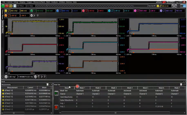
Figure 1: Use masks on oscilloscope channels in Infiniium software to ensure each power rail has the correct timing.
How to measure power quality
You’ll need to check for crosstalk and EMI issues in your power rails to ensure good power integrity in your system. Power coming from a DC/DC converter will have a large DC offset and a smaller AC offset. As shown in Figure 2, using a regular 10:1 probe can introduce a lot of noise and make it difficult to see the AC offset, potentially exaggerating the peak-to-peak voltage of the signal. Keysight’s N7020A power rail probe is 1:1, which allows the oscilloscope to see the AC offset of the signal in better detail.

Figure 2: Using a 1:1 power rail probe lets you analyze your power rail’s AC offset in greater detail
EMI comes from crosstalk from the high-speed data signals. Keysight’s D9110POWA software can help you understand the sources of noise and its effects. This program uses an aggressor signal to influence crosstalk on a victim signal to analyze how much noise is being caused by crosstalk. Both the data line and power traces can be aggressors and victims of each other’s interference. The software helps calculate improvements for cleaning up noise across the two signals.
D9110PWRA is another useful software tool for MXR-Series oscilloscopes that helps to analyze power supplies. Switched mode power supplies have many power quality parameters which D9110PWRA can measure. This application can also measure power supply rejection ratio (PSRR). PSRR is a measure of how well a DC-DC converter can reject noise on the input from getting to the output.
How to measure power efficiency
Checking energy efficiency is essential for any power system. For battery-powered systems, good efficiency can increase the life of your product, making your customers happier. For line-powered systems, efficiency is important as well. Data centers are one of the biggest energy hogs in the world, producing massive amounts of heat, so eliminating waste can save a lot of money on cooling.
High-sensitivity current probes (such as Keysight’s N2820A-Series current probes) use current sense resistors, which can provide more accurate, detailed current data than Hall Effect sensor current probes. These probes can switch between a high-sensitivity and attenuated mode, which show low current and high current measurements with the same level of accuracy. With that level of detail, you can optimize sleep states and wake-up frequencies for less overall power usage.
Consider environmental factors
Environmental testing is an important final step. Power supplies are sensitive to temperature shifts. In low temperatures, in-rush limiting devices have lower impedance, making it more difficult to draw enough current to initiate startup in your device. Electrolytic capacitors can decrease in capacitance at low temperatures, resulting in filters becoming less effective at filtering out ripple and noise. In high temperatures, power supplies lose efficiency as flowing current will heat up elements with impedance.
The key to environmental testing is using probes designed for extreme temperature probing. Using a standard probe in a temperature chamber and subjecting it to temperatures that they are not rated for can damage the probes. Keysight’s extreme temperature probes support temperature ranges as wide as -55 to +150 °C.
Next steps
Now that you’ve learned some of the basics of power integrity and how to measure your power rails, check out some of these helpful resources:
- Making Your Best Power Integrity Measurements - Application note with a detailed discussion of power supply measurement techniques
- Power Integrity Simulation & Measurement Skills - Keysight University course about designing and testing for optimal power integrity
- Power Integrity Testing Using Infiniium EXR-Series Oscilloscopes - Information about power application software for the affordable EXR-Series oscilloscope
- Testing Switch Mode Power Supplies Using the Infiniium EXR- and MXR-Series Oscilloscopes - Resource for using D9x10PWRA software on Infiniium oscilloscopes.