
How to use a digital multimeter
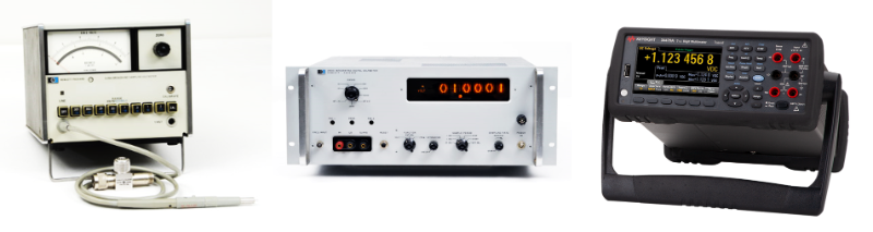
Multimeters have come a long way since the invention of galvanometers, an analog needle-pointing display measuring voltage and resistance in the 1820s. Digital multimeters (DMMs) started replacing analog multimeters in the 1950s due to their accuracy and extra features such as auto-ranging, data logging, and more.
What is a digital multimeter?
A multimeter is a measuring meter that makes multiple types of measurements such as alternating current (AC) or direct current (DC) voltage, AC or DC current, resistance, temperature, capacitance, and other parameters. A modern digital multimeter (DMM) uses digital and logic technology to miniaturize and enable many features in its internal system. With digital technology, multimeters provide graphical displays, perform data logging and signal digitizing capabilities, offer programmability, and communicate with external devices.
How to use a digital multimeter
Modern digital multimeters are highly versatile and can make multiple types of measurements and provide graphical output displays, such as trends and statistical charts. DMMs are programmable and can communicate with external computers for post-analysis work. Notably, they pack a lot of functions into a small benchtop box, typically no bigger than the size of a book. Portable handheld DMMs are even smaller, lighter, and are battery-operated.
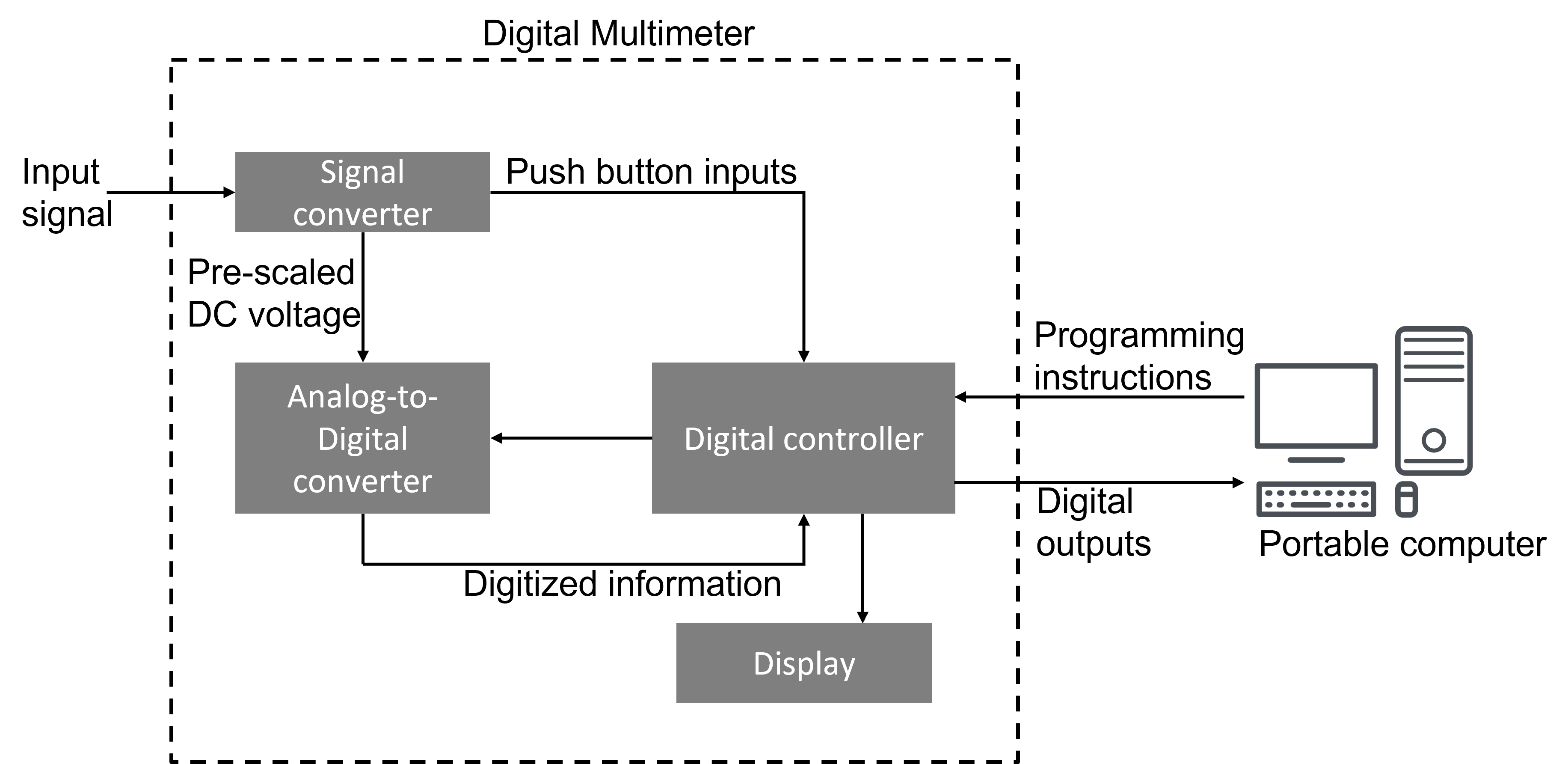
The block diagram in Figure 2 shows a typical digital multimeter, where the input signal AC or DC voltage, AC or DC current, resistance, temperature, or any other parameters is converted to DC voltage within the range of the internal analog-to-digital converter (ADC). The ADC then converts the pre-scaled DC voltage into its equivalent digital numbers which will be displayed on the display unit.
The digital controller block is implemented with either a microcontroller or a microprocessor, managing the flow of information within the instrument. The block will coordinate all the internal functions and transfer information to external devices such as printers, portable computers, or other test instruments. In the case of some handheld multimeters, some of these blocks may be implemented in a VLSI circuit where the ADC and the display driver appears in the same integrated circuit.
Although the ADC forms the key element within the instrument, to fully understand how a DMM works, you need to look at some of the other functions around the ADC. Figure 3 shows a simplified operations flow of the ADC’s sample acquisition process within a DMM.\

Although the ADC will take many samples, the overall digital multimeter will not display or return every sample it takes. Instead, the ADC uses a buffering and averaging strategy on the samples to achieve high accuracy and resolution. This strategy helps overcome the effects of slight variations such as powerline noise and other environmental noise.
Your digital multimeter’s performance depends on how well it deals with noise from extraneous factors and eliminates them from the true measurement — an essential element to achieving the highest level of accuracy.
Digital multimeters are capable of making various kinds of measurements. Below are some common examples of how to probe and effectively measure different kinds of signals.
1. Measure Voltage
Measuring voltage is one of the easiest measurements to make using a DMM. Place the probes across the two points where you want to measure the voltage.
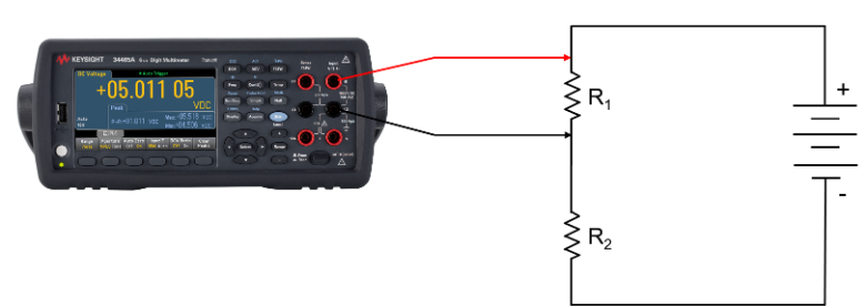
Virtually all DMMs have an auto-polarity function, so there is usually no need to worry about how the probes connect. However, it is best practice to connect the common (COM) connection, usually the negative connection, to the lower voltage, the chassis, or the zero-volt line.
2. Measure Current
Voltage measurements are easy to make with a digital multimeter but using it to measure current is slightly more challenging. When measuring current with a DMM, place it in series with the circuit, so the current flows through the DMM.
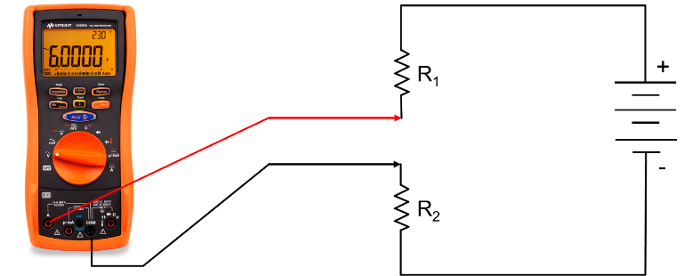
Digital multimeters have a built-in current shunt resistor to measure the current. However, if the current is too high for the DMM, you will need a different setup. The solution is to place the DMM in parallel with an accurate external current shunt resistor that can handle the required power rating. You can measure a voltage across the external current shunt resistor and then use Ohm’s law to calculate the current.
3. Measure Resistance
Digital multimeters offer both two-wire and four-wire resistance measurement capabilities. However, these two resistance measurement techniques are not equally well-suited for all resistance measurement applications.
A two-wire resistance measurement configuration appears in Figure 6. Digital multimeters typically employ the constant current method to measure the resistance, which sources a constant current (Itest) to the device under test (DUT) and measures the voltage (Vm). You can then calculate the resistance by using the known current and the measured voltage.
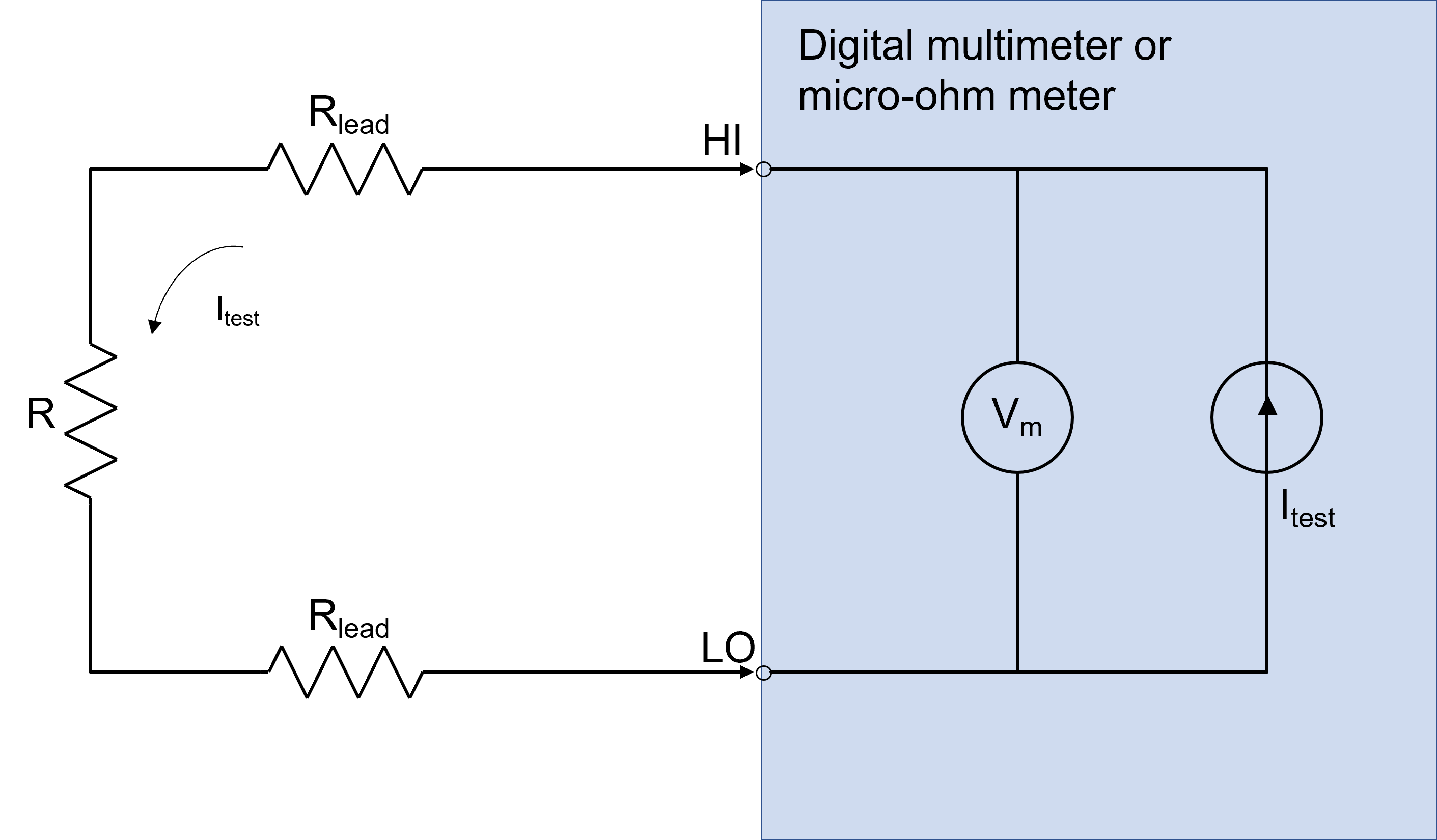
The resistance you want to measure appears as an unknown resistor labeled R in Figure 6. An advantage of this method is the simple cabling — it uses only two wires.
All DMMs measure resistance by forcing a DC current through the unknown resistance. In a two-wire measurement, the current source connects internally to the source leads at the DMM. Any resistance in the test leads shows up as a reading error. When the current is applied, the voltage generated across the sample is measured and then used to calculate R using Ohm’s law, R = V/I. The unknown resistor R measurement will have an error if you do not remove the cabling resistance errors.
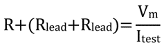
If you use a “math null” at the point of measurement, you will be able to reduce cabling resistance errors, Rlead, in the measurement.
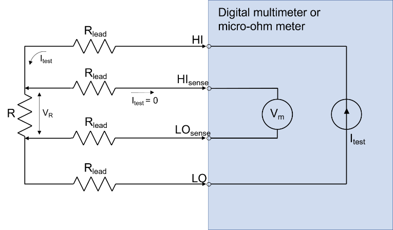
Figure 7 shows four-wire leads coming out of the test instrument. The four-wire leads consist of a pair of current source wires and a pair of voltage sensing wires in parallel — they connect to R or the DUT. Similar to the two-wire measurement method, the current source wires generate a voltage drop across R along the HI and LO lead wires. However, the second pair of leads separate from the current source leads to form a direct voltage loop that measures the voltage drop across R. The second pair of voltage sense leads is HIsense and LOsense. Since the DMM’s resistance is very high, on the order of 10M ohms, the lead wire resistance has little effect on the measurement. Since the Rlead is negligible and independent of the current source, Itest, you have:

where VR is the voltage across the resistor R or DUT, and the meter measures the voltage as Vm:
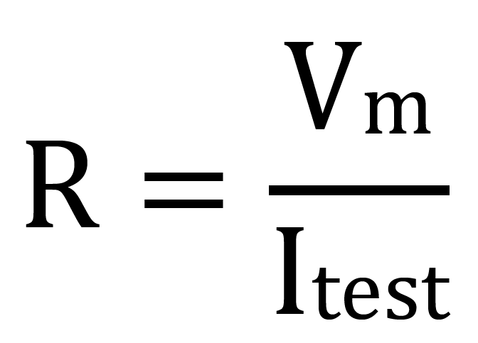
So you can determine the resistance value much more accurately than using the two-wire measurement method.
4. Measure Capacitance
Digital multimeters make capacitance measurements by applying a known current to charge the capacitor and use a resistor to discharge it. The capacitance is measured by measuring the change in voltage (DC) at different points of a voltage-over-time response curve during the charge / discharge cycle and using an algorithm to compute the capacitance.
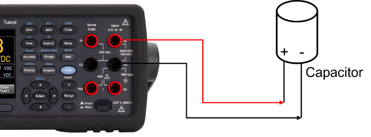
To improve measurement accuracy of small value capacitors, press the “Null” button with the test leads open to subtract the residual capacitance of the multimeter and leads.
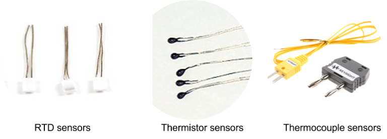
5. Measure Temperature
Modern digital multimeters can serve as temperature data loggers. For example, many DMMs can accept resistance temperature detectors (RTD), thermistors, or thermocouple sensors.
For better accuracy, use RTD or thermistor sensors. To measure a more extreme range of temperatures, use thermocouple sensors because they have a wider range of temperatures.\
6. Measure Diode
A typical benchtop DMM makes a direct forward bias measurement of a diode, as shown in Figure 10. The DMM will typically source a 1 mA current and measure the voltage drop across the diode.
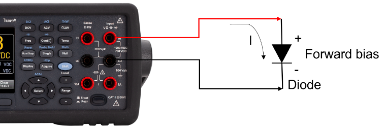
Use this test function to check diodes, transistors, silicon-controlled rectifiers (SCRs), and other semiconductor devices. A good diode allows current to flow in one direction only. This test sends a current through a semiconductor junction and then measures the junction’s voltage drop. A typical junction drop is 0.3 V to 0.8 V.
7. Perform a Continuity Check
A continuity check using a DMM will help detect an electrical short in your circuit or component. A continuity check measures resistance across the two points of the input probes. Typically, you have an electrical short if the measured resistance value is less or equal to 10 Ω. The DMM makes a continuous and audible beep until the circuit you are measuring is no longer an electrical short. Sometimes, the DMM may make intermittent audible beeps during the continuity check, signifying an intermittent electrical short.
8. Measure the Frequency or Period of an Oscillating Signal
Modern digital multimeters also have a frequency or period measurement function. This function normally measures the frequency of an AC signal or any type of periodic signal. Usually, it measures how fast a motor is spinning, where the frequency you measure becomes rounds per minute (RPM).
What Are the Typical Digital Multimeter Specifications?
A typical digital multimeter has many types of specifications. But the critical specifications you need to consider are accuracy, sensitivity, and resolution.
Accuracy
Accuracy represents the uncertainty of a given measurement as the reading from the DMM can be different from the actual value of the signal. Accuracy is a measure of how good these numbers are, or how much you can trust them. Below are some of the common expressions that you can pick up from most DMM datasheets:
± (% of Reading + % Range)
± (ppm of Reading + ppm of Range), where ppm is part per million
Sensitivity
Sensitivity is the smallest unit under a given parameter of the measurement function that the instrument can be detect and be meaningful to the end-user.
Resolution
Resolution is the level of detail that is measurable or the number of significant digits on a digital multimeter. Resolution can be expressed in terms of bits, digits, or absolute units, which can be related to each other.
More Digital Multimeter Resources
- Learn more about Keysight’s comprehensive range of digital multimeters from 3.5 to 8.5 digits resolution, with speeds up to 100,000 readings/sec, and is available in handheld or bench applications. Please visit our website: https://www.keysight.com/us/en/products/digital-multimeters-dmm.html
- If you are curious about the digits, accuracy, and resolution using a DMM, please read our blog post: https://blogs.keysight.com/blogs/tech/bench.entry.html/2019/01/10/what_are_digits_acc-lInJ.html
- If you plan to buy a DMM soon, please download our eBook: 10 Things You Must Know Before Buying Your Next Benchtop Digital Multimeter.
- Check out: Keysight Digital Multimeter Products Catalog.