
Real-Time vs. Sampling Oscilloscopes: What Are the Differences?
All modern oscilloscopes are categorized as digital storage oscilloscopes (DSO) which digitally sample, store, and display a signal to the user - but the technique for accomplishing this can vary from one scope to another. Two distinct categories you’ve probably heard about are real-time scopes and sampling scopes, each of which have advantages for specific applications. Understanding the differences between these two instruments can help determine which one is right for your use case.
Similar Names, Different Methods
First, let’s clear up some of the terms that has evolved over the years to describe these instruments:
- A real-time oscilloscope, as the name suggests, digitizes the input in real time by sampling fast enough to accurately capture and display an incoming signal. Each data point on the display has been sampled directly after the previous point. These instruments are sometimes called single-shot scopes based on their ability to capture a continuous signal with a single acquisition. This is the most common type of scope on the market.
- A sampling oscilloscope or Digital Communication Analyzer (DCA) uses a different method to sample and display a signal, digitizing a single value per trigger over the course of many passes which “sweep” across a window of time. This is done by adding a small, fixed delay with each iteration, leading to another similar moniker: equivalent-time sampling oscilloscopes. But both names can lead to some confusion though: all digital scopes use sampling in one way or another, and some real-time scopes might include a mode called “random equivalent-time sampling”. At Keysight we describe sampling scopes as digital communication analyzers to highlight the sampling scope’s strength in characterizing the high-speed digital signals used in data centers and wireline telecommunication systems.
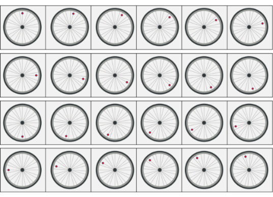
Here’s an analogy to help understand the difference between these two types of scopes. Let’s say we want to record the rotation of a bicycle wheel, capturing the full rotation of the wheel in one-degree-of-rotation increments. One way to approach this would be to use a video camera with a very high frame rate – fast enough to capture 360 images within the time period of a single rotation. Using this method, you could capture all unique angular positions after seeing the wheel turn a single time.
Alternatively, let’s say instead of a video camera you have a camera that can only take a single photograph at a time. However, this camera can be programmed to capture an image after a very specific amount of time after a signal is given. Assuming a signal is provided to the camera every time the wheel is at 0°, you could program the camera to take a picture at 1°. On the next rotation you can take a picture at 2°, then 3° and so forth. After 360 images are taken, they can be sequenced together to create an animation of the entire rotation.
In this analogy the video camera is like a real-time scope and the single-frame camera is like a sampling scope. A consistent, repeating signal – like a spinning wheel – is what a sampling scope is made for. A non-repeating signal – like a wheel that changes speed or direction randomly – is where a real-time scope would be needed.
What Are Some Key Differences Between Real-Time Scopes and Sampling Scopes?
Viewing Waveforms
A real-time oscilloscope uses an internal sample clock that’s independent of and faster than the signal it’s capturing, giving it the powerful ability to evaluate the input signal itself to determine when to start the acquisition. This provides more debugging flexibility since the trigger can be based on arbitrary criteria such as a voltage level or a pattern. This also allows for collecting pre-trigger samples, providing insight into the behavior both before and after a sporadic event.
Sampling oscilloscopes perform their sampling synchronously with the data and require either an explicit or recovered clock signal. Explicit clocks are provided alongside and separate from the data signal (such as the SCL signal on an I2C bus). Alternatively, a clock signal can be obtained from the data signal itself through a process called clock recovery, performed by a separate device or by a subsystem within the sampling scope.
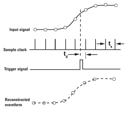
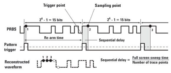
To capture a waveform, sampling scopes needs a repeating pattern since the acquisition is done over multiple passes. A pattern trigger derived from the clock signal provides a trigger point after which a sample is taken. Upon each pattern trigger, a new sample is taken at a sample point which is slightly further from the pattern trigger with iteration. The sampling scope then reconstructs the waveform using the acquired samples. \
Creating Eye Diagrams
Eye diagrams are a key tool in evaluating the signal integrity of high-speed electrical and optical buses. A real-time oscilloscope can create eye diagrams called “real-time eyes” through a multistep process:
- The scope samples a record long enough to capture many instances of every possible symbol transition.
- The boundaries of each symbol are determined either by using an externally provided clock or through clock data recovery.
- The scope overlays the captured transitions to provide a visual representation of the bus transitions with insight into the transmitter’s ability to provide a signal that the receiver can accurately interpret.

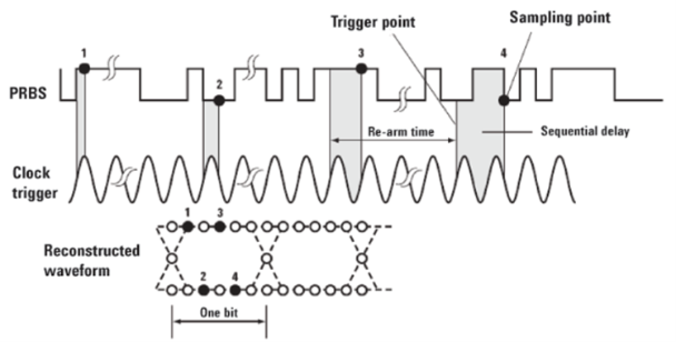
Like waveform captures, the creation of eye diagrams on a sampling oscilloscope is made possible by a multiple-pass sampling methodology – but instead of a pattern trigger, eye diagrams use the clock signal (either explicit or recovered) as a trigger. With each clock trigger, a sample is taken after a specific delay which is increased incrementally with each iteration. This process is repeated multiple times for every sample point to build the visual eye diagram. \
Bandwidth and Resolution
Both real-time and sampling scopes are available in bandwidths up to over 100 GHz, enabling use with the latest high-speed digital applications. Because sampling scopes have the luxury of sampling over several periods they can use an ADC with a lower sample rate and higher vertical resolution, often up to 14 bits. Real-time scopes, on the other hand, require an ADC with a sample rate much faster than the specified bandwidth to accurately capture the signal in real time, requiring a compromise on the vertical resolution.
Modularity and Interfaces
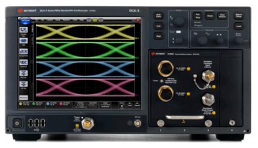
Real-time oscilloscopes normally have 4 to 8 permanently installed electronic input channels. Conversely, sampling oscilloscopes can have a combination of electrical, optical, and TDR channels. Keysight offers the DCA-M standalone mini DCA with different combination configuration and the DCA-X wide-bandwidth sampling oscilloscope platform featuring a variety of plug-in modules that perform precision optical, electrical, and time domain reflection/transmission (TDR/TDT) measurements.\
Which Type of Oscilloscope is Right for My Application?
Real-time oscilloscopes and sampling oscilloscopes overlap in many of their capabilities including the construction of eye diagrams, use of histograms, and measurement of jitter. The biggest difference between the two is the real-time scope’s ability to capture a non-repetitive signal or trigger off the data signal itself, making the RTO much more suitable for debugging the behavior of a signal. This becomes particularly true when trying to troubleshoot an intermittent issue that requires defining complex trigger conditions.
An additional advantage of the real-time scope over the sampling scope is its extensive support for decoding and testing many protocols and standards. Keysight’s Infiniium line of real-time oscilloscopes are available with software to decode, debug, and test compliance to many of today’s industry-critical communication protocols including the latest generations of USB, DDR, and PCI Express.
Sampling scopes show their true strength in use cases with the most stringent noise and jitter requirements. A key application served by sampling scopes is optical transceiver manufacturing test, where the combination of performance and price make the digital communication analyzer an ideal solution.
While either type of scope might serve the needs of one particular application today, you’ll want to also evaluate your future needs since a real-time scope will typically provide more debugging capabilities, support more industry standards, and feature a broader set of application-specific software packages.