
Get More Usable Power on Your Bench
Most power supplies provide a single range because it is the most straightforward, cost-effective design. A single-range power supply can deliver its maximum output power using one voltage and current value. A single-range solution may not provide high enough current or voltage for your designs, even if the power specification is sufficient.
Traditional high-power supplies are not suitable for the research and development (R&D) bench because they are bulky and loud. A power supply’s internal components include voltage tolerances, the maximum output power, and the fans that dissipate heat generated from the components. Conventional power supplies can also cause problems for the device under test (DUT) because they generate more output noise.
The high current standard power supplies can cause voltage drops in the cables. Making external measurements with probes and shunts is necessary to measure power at the circuit correctly. With the rise in popularity of power semiconductors and large-capacity batteries, more devices require testing with a high-current power supply.
This blog explains how to use the Keysight E36200 Series autoranging bench power supply in an R&D lab or on your bench to help you get more usable power from a power supply.
Autorange versus Single Range and Dual Range
Autoranging power supplies produce more current at all voltage settings than traditional single-range supplies. Figure 1 shows how power supplies can have three common output architecture: single range, dual range, and autorange.
A single-range power supply is the most straightforward architecture because maximum output power occurs at only one setting — maximum voltage and current. If you plot the maximum voltage and current, the results form a rectangle on a V–I graph. All valid voltage and current combinations reside within the rectangle.
A dual-range power supply increases the number of voltage / current combinations for the same maximum power. This combination offers a high and a low voltage range, with the low range providing more current.
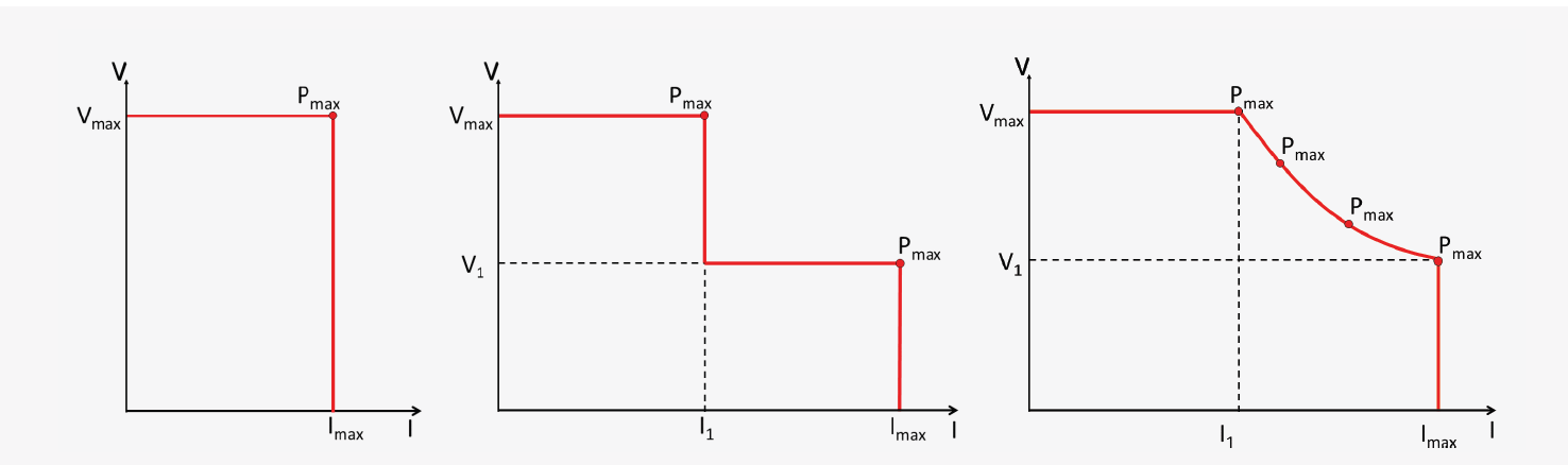
Figure 1. Power supply output characteristics (left to right): single range, dual range, autoranging
Variable slew rate protects high current devices
A power supply capable of outputting 10 A or more provides enough energy to damage devices with large inrush current. Devices such as DC-to-DC converters, lighting drivers, and LED bulb modules use a switching power supply design. Switching power supplies often have a high input capacitance, and applying DC power to the capacitor draws a large inrush current.
One way to minimize the inrush current is to ramp the voltage slowly. Variable slew rate changes how fast the output voltage ramps over time. Lowering the slew rate limits the inrush current. A higher slew rate allows the power supply to quickly raise its output to a new set voltage.
Increasing the output voltage and setting a current limit affects the up-programming time. Since slew rate and current limiting interact, it is best to set the current limit based on the device’s steady-state current usage. You can then lower the slew rate to limit any unwanted inrush current. To reduce up-programming time, use a higher current limit and slew rate. To obtain the fastest time, set a maximum value for both the current limit and slew rate.
Overcurrent adds a layer of protection shuts because it shuts down a channel when it exceeds the current limit. Configuring the channel sends an inhibit signal to other channels or power supplies to turn off all power sources to a device.
Making accurate voltage measurements
Higher currents lead to significant voltage errors because of the voltage drop that occurs in the leads. The remote sense or four-wire sense ensures the selected voltage goes to the load. Sense leads measure the voltage at the load, and the power supply increases its output to compensate for any losses in the wiring. In Figure 2, the power supply increased its output voltage by 160 mV to compensate for the 80 mV (0.02 Ω * 4.0 A) drop in each load lead. The default setting is a local or two-wire sense, which measures the voltage at the power supply’s output terminals. In the two-wire scenario, the voltage at the load would be about 160 mV below the set output.
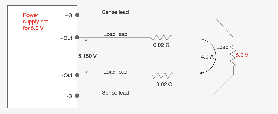
Figure 2. Remote four-wire sense raises the power supply’s output voltage to compensate for the voltage drop in the leads
When using sense lines, it is important to twist the wires to avoid electromagnetic noise coupled into the voltage measurement. Sense lines also need a reliable connection — the power supply cannot regulate the output if a lead becomes disconnected. Most power supplies have a safety feature to regulate the supply when a sense line becomes disconnected.
Overvoltage protection (OVP) provides an additional safeguard by continuously measuring the voltage at the power supply’s output terminals. Since OVP does not take advantage of the sense lines, you calculate the OVP setting by adding the voltage drop to the load voltage leads. Figure 2 is an example of when OVP requires a setting above 5.16 V.
Tips to accurately measure current
Knowing the voltage at the device is the first step to making a meaningful current measurement. A typical method to measure current is to use an external shunt. You can calculate current by measuring the voltage drop across the shunt resistor and dividing by the value of the resistor. Measuring higher currents can be difficult using an external shunt resistor, as the current can heat the resistor. Heating a resistor changes its value, creating an error in the current calculation.
A second method to measure the current is to use a zero-flux precision current transducer, as self-heating errors do not affect it. A transducer is more expensive than a shunt resistor, but it is easier to select and estimate measurement errors. The final method is to choose a power supply with adequate measurement accuracy. The E36200 Series autoranging power supply provides excellent measurement accuracy and can log voltage and current data over time.
Low power supply output noise
Making accurate voltage and current measurements begins with having a supply with excellent stability and low output noise. Linear power supplies typically have low common-mode noise. The E36200 Series autoranging power supply uses a switching topology to provide a compact bench supply. Clever circuit design and digital filtering provide output noise of less than 350 μVrms (20 Hz to 10 MHz) on a 200 W power supply.
Summary
Applications that require more current and higher power can benefit from a flexible bench power supply. Smart capabilities such as auto-ranging, auto-series, and auto-paralleling allow a power supply to cover many applications without resorting to a larger power supply. An oversized single-range power supply can be economical to purchase but comes with many challenges. With additional circuitry, common-mode noise, regulation, and inrush current are difficult to control. Many devices require testing at different voltages and may need multiple voltages turned on and off simultaneously. The E36200 Series autoranging power supply design manages more applications and provides more current at every voltage.
Learn more about the E36200 Series autoranging power supply. Bench Power Supplies