
Generate IQ Signals with a Function Generator
Introduction
IQ signals are a form of modulated waveforms that are used with many existing communication technologies today. IQ signals are used in mobile phones, radars, lasers, Wi-Fi networks, modems, navigation systems (GPS), RFID tags, and satellite communications. Large amounts of information must be transferred at a fast pace. Testing with simulated IQ signals helps designers anticipate device behavior in a spectrum filled with interference.
Designers need to test the limits of their designs to ensure real-world performance. To do this, they must first generate an ideal signal to characterize their design’s ideal performance. An ideal signal is a high-quality, known good signal.
Designers must also test their devices under non-ideal conditions. To do this, they add real-world, non-ideal characteristics to the signal. This helps them test the limits of their designs.
This blog covers how to generate both ideal and non-ideal IQ signals. To do this, we will use the Keysight 33500B and 33600A True form Series waveform** generators to generate an IQ signal.
Jitter and Waveform Generation Technology
You should consider the following characteristics when choosing a waveform generator for IQ signals:
- Bandwidth - Choose a generator with a flat analog waveform bandwidth and a flat frequency response. make sure your waveform generator has ample bandwidth.
- Signal integrity – The most important attributes for IQ signal generation are consistency, high accuracy, and stability of the output signal.
Creating and generating IQ baseband signals
Transferring Data
Many waveform generators provide USB, LAN, and GPIB I/O interfaces to connect to a PC. They also support drivers such as IVI for transferring IQ waveforms remotely from the software. You need to ensure your waveform generator supports the transfer method you want to use.
Many generators allow you to upload waveforms from a USB storage device using the USB connector on the front panel. With the Keysight 33522B, you can easily upload waveforms from file formats such as comma-separated value (CSV) files, data (DAT) files, and ActionScript Communication (ASC) files. These file formats are typically available in communication and signal engineering software packages such as MATLAB.
Generating IQ signals
Methods vary for different waveform generators, but once the signals pass to the waveform generator, you can physically create your signals. In this example, we are going to use the IQ signal player option. It provides an easy-to-use interface that allows you to configure and control both channel 1 and channel 2 as if they were a single channel or waveform. Figure 2 shows a screenshot from the 33522B with the IQ signal layer option. In Figure 1, the waveform generator is outputting a 64-QAM IQ baseband signal at a sample rate of 1 MHz.
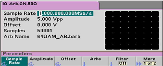
Figure 1 33500B IQ Signal Player screen view
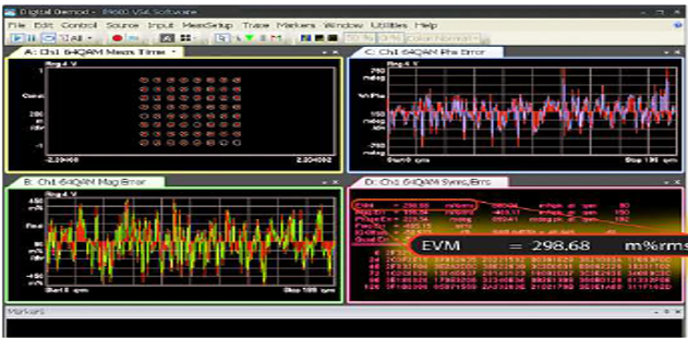
Figure 2 Constellation diagram and EVM of a 64-QAM baseband signal
Figure 2 displays the IQ baseband signal captured with a high-performance oscilloscope running signal analysis software. You can see the resulting constellation diagram in the top left display and the measured error vector magnitude (EVM) of only 0.3% in the bottom right display. The two additional displays, lower left and top right, show the plotted magnitude error in millipercent, and the phase error in millidegrees.
As you can see, this is a very high-quality IQ signal and is an excellent choice for testing your designs using an ideal signal. Once that phase of testing is complete, it is time to test with non-ideal signals.
Simulating non-ideal signal and channel conditions
When you need to understand the limits of your design, the goal is to simulate a signal with quantitative, non-ideal characteristics. Non-ideal characteristics let you test the response of the design under non-ideal conditions. There are three main parameters you want to modify when simulating non-ideal IQ baseband signal conditions:
- Balance adjust: Allows you to specify the amplitude gain balance between the two channels and the amplitude offset adjustment for each channel (Figure 3).
- Skew adjust: Allows you to shift either the I or Q baseband signal in time with picoseconds of resolution.
- Advanced modulation: Modulation features such as sum or phase modulation allow you to add noise, random jitter, or deterministic jitter to the signal.
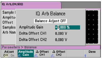
Figure 3. IQ balance adjust screen
Figure 2 shows an additive noise example on the 64-QAM signal. We have added a Gaussian noise waveform with a crest factor of 4.3 and adjustable bandwidth up to 30 MHz which is built into our generator. The noise signal will not repeat for more than 50 years of continuous playback.
Using the sum modulation capability of our generator, we added 30 MHz bandwidth of noise at 10% amplitude to the I and Q baseband signal (Figure 4). Comparing Figure 2 with Figure 4, you can see the constellation points are more significant and obscure. EVM has increased to about 1%. The noise amplitude adjustment on the 33522B provides resolution down to 0.01%. With these controls, you can zero in on the exact amount of error you would like to simulate.
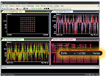
Figure 4. Constellation diagram and EVM of 64-QAM baseband signal with added noise
Conclusion
If you need to create IQ signals, you need a waveform generator that’s up to the task. You need to have adequate bandwidth and high signal integrity. You also want to ensure that you can quickly create IQ signals and easily modify them to simulate non-ideal conditions. In the case of the Keysight True form Waveform Generators, we were able to do this using the built-in IQ Signal Player option.
For more information on Keysight Trueform Series waveform generator, please visit https://www.keysight.com/my/en/products/waveform-and-function-generators.html