
How to Measure Current on an Oscilloscope – Low Current Probing
As power consumption and energy efficiency become more important, especially with battery-powered devices, it’s necessary to measure extremely low-level signals with higher sensitivity. Lowering your device’s current consumption will, in turn, lower its power consumption.
Power is defined as P = V x I
Having the ability to view the µA range with the highest accuracy possible allows you to analyze the power consumption of your design in detail. This ultimately leads to minimizing the power consumption, therefore maximizing battery life.
Download the "6 Essentials for Getting the Most Out of Your Oscilloscope" eBook.
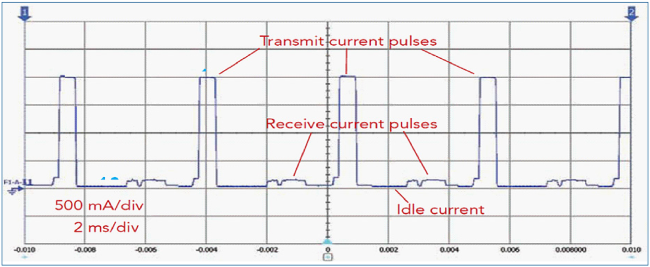
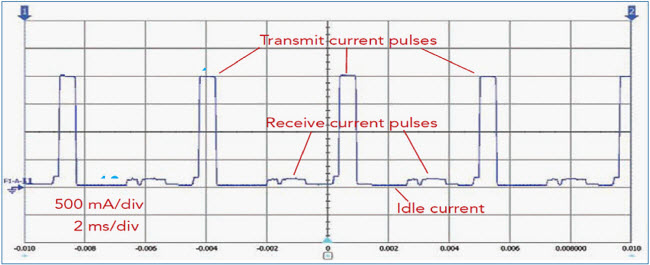
One of the main challenges engineers run into is measuring the current consumption of a signal with wide dynamic range. In battery-powered devices, like a cell phone, the device will switch back and forth between active and idle states. During the active state, it will draw higher currents, in the A’s range. But when the device is idle, it draws very small currents, in the µA’s. In Figure 1, you can see the current signal of a cell phone making a phone call. The active peaks have a current of around 2 A, but during the idle states, the current is very small.
To measure on both of these extremes accurately, a specialized current probe is best. Clamp-on style current probes are typically enough for most measurements, especially if you are only trying to analyze the active periods. However, when measuring on the lower levels during the idle periods, a clamp-on current probe typically has too much noise. The Ohm’s law approach is the best option to measure on the µA or nA level. This means simply measuring the voltage drop across a sense resistor to derive the current. The only sense resistor current probe available with high sensitivity and a wide dynamic range is Keysight’s N2820A current probe, which can be seen in Figure 2.
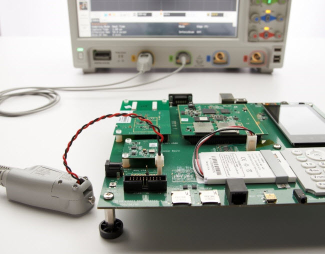
This is a 2-channel active current probe. Each of the channels has a different gain in order to measure the two different current ranges. When you probe on your device with both channels:
- One channel will give you a zoomed-in view of the µA level
- The other will provide a zoomed-out view of the active, higher levels
The probe also has extremely low noise, which means you will have the highest accuracy possible when measuring on those really low levels. This will help to ensure you are saving even pA’s of current, which may seem small, but can make a huge difference in the system overall.

As I mentioned, this probe simply measures the voltage drop across a sense resistor. You can either cut a line and solder a resistor directly into the circuit, or you can use one of the temporary connectors that come with the probe. The probe comes with a 20 mΩ and a 100 mΩ resistor sensor head ready to use, along with a user-definable resistor head. You can use resistances from 1 mΩ to 1 MΩ.
Selecting the correct sense resistor for your device can be difficult, but is critical in order to measure different current ranges and characteristics accurately.
If you use a larger resistor, you will get a great signal to noise ratio, which makes for more accurate measurements. The downside to using a larger resistance value is the burden voltage. Burden voltage is the unwanted voltage drop caused by increased power dissipation at the resistor. Using a smaller sense resistor will lower the power dissipation and, in turn, the burden voltage. However, this lower resistor value also comes with downsides, especially with measurement accuracy. Figure 4 below can be used to help determine whether a high or low resistor value would be better for the measurements you are trying to make.
Once you have this wide range of currents accurately captured on the oscilloscope screen, you can learn from it to understand how to adjust your design to increase power efficiency. Area under the curve measurements allow you to understand the charge and easily calculate current consumption over time. You will be able to see where there may be areas where power is being wasted. There could be points where the device should be in its idle state, but some functionality is staying on that is causing for power to be drawn unnecessarily.
Now, you can easily analyze power consumption and see the big picture on the dynamic current waveforms to improve the energy efficiency of your devices. And, built-in automatic measurements make it even easier to take your analysis to the next step and find the root cause of any problems you see.
To learn about which current probe is right for your applications, take a look at the Application Note, How to Select the Right Current Probe.
To help you test faster and avoid mistakes that negatively impact your results, download 6 Essential Tips for Getting the Most Out of your Oscillcope eBook.