
Protect Radar Systems with Dynamic Frequency Selection (DFS) Functionality
The Need to Protect Incumbent Radar Systems
You are heating up your lunch in the microwave oven while watching over your 6-month-old daughter through the baby monitor. At the same time, the wireless Bluetooth speaker in the living room is playing the songs from your cellphone that is connected to the internet. This typical household scenario is an example of devices — microwave ovens, baby monitors, Bluetooth speakers, and cellphones connected to the internet through the 2.4GHz industrial, scientific, and medical (ISM) band. The number of wireless devices connected to the 2.4 GHz band causes severe congestion to the wireless network.
To meet the exploding demand for more unlicensed spectrum, regulators across the world such as the United States Federal Communications Commission (FCC) and the European Telecommunications Standards Institute (ETSI) opened up additional spectrum in the 5 GHz band for use by unlicensed wireless devices. This 5 GHz band is also where radar systems, such as military radar and meteorological radar applications are operating. When unlicensed use of the 5 GHz band spread into radar frequencies, radar services can sometimes experience severe interference from consumer devices. To protect the incumbent radar systems, regulators established a mechanism that can detect radar transmissions and cease the transmission of IoT devices in the same radio frequency.
What is Dynamic Frequency Selection (DFS)?
DFS is a mandated functionality for wireless IoT devices that share the 5 GHz unlicensed national information infrastructure (U-NII) band with other radio transmissions that are considered primary-use or mission-critical. These mission-critical devices can be radar systems used by specific industrial, federal civilian, and other military organizations. Radar signals are vulnerable to interference from other devices that use the same spectrum. A properly implemented DFS functionality is required to ensure a wireless device detects radar signals and switches its operating frequency to avoid causing interference to radar systems.
The International Telecommunication Union (ITU) imposed this requirement, and it is enforced in many countries around the world, such as the United States of America, the European countries, China, Japan, and Korea. The test parameters and test procedures are very similar, although the regulation and definition of radar signals used for the tests vary by countries and regions.
In-service Monitoring Test
In-service monitoring test is one of the required tests in DFS. The purpose of this test is to ensure that a wireless unlicensed device using the 5 GHz band can detect a radar signal in the same channel and react accordingly.
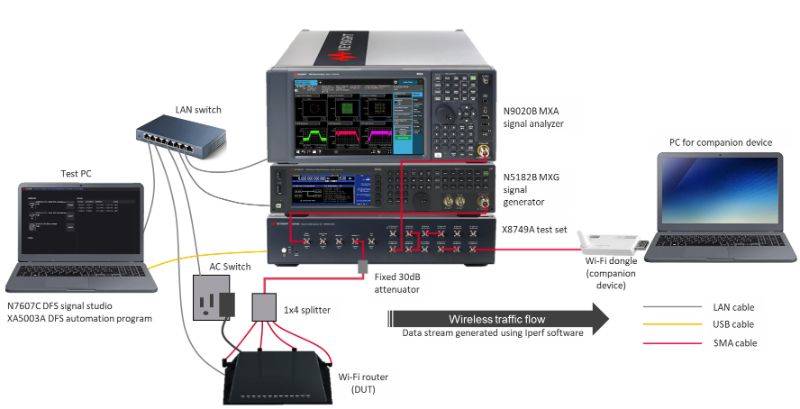
Figure 1 shows the setup of the in-service monitoring test for DFS. In this test, the Wi-Fi router functions as a device under test (DUT), while the Wi-Fi dongle functions as a companion device. The DUT must be in normal transmission mode. The data stream from DUT to companion device is created using iPerf, an open-source software for network performance measurement and tuning. The signal generator creates and simulates the radar test signals, while the signal analyzer monitors the behavior of the DUT in response to the radar test signals.
Simplifying DFS Testing with XA5003A DFS Test Software
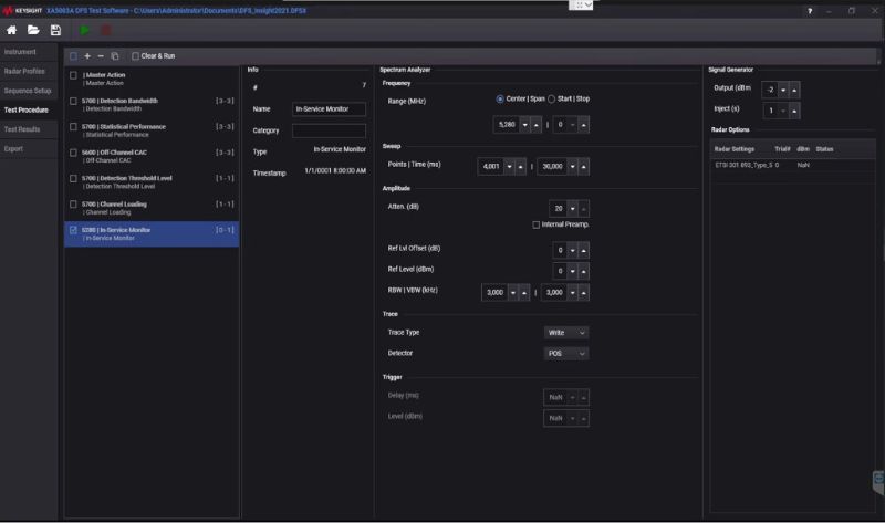
With the dedicated Keysight XA5003A DFS test software, DFS testing is simplified and automated. Figure 2 shows how the software looks like when it is configured to test the DUT at 5280 MHz with a Type-5 staggered PRF radar test signal defined in ETSI standard.
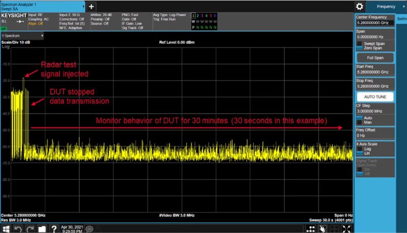
The spectrum analyzer captures the data bursts transmitted from the DUT. As shown in Figure 3, when the signal generator injects the radar test signal, the DUT stops transmitting data. The test will continue to capture and monitor the DUT behavior for the next 30 minutes to ensure that there is no data transmission — defined by the standard as ‘non-occupancy period’.
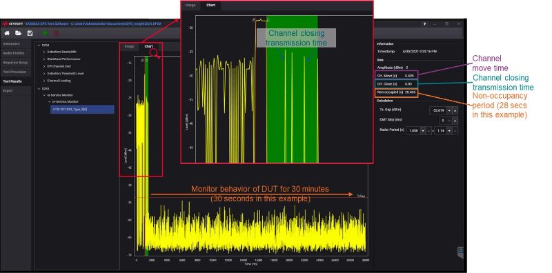
Figure 4 shows the results of the DFS in-service monitoring test. With the software, you can zoom into the signal to take a closer look at the results. T0 and T1 indicate the start and stop time of the radar pulse. After T1, the DUT is expected to clear the channel and move to a new channel within 10 seconds, which is defined by the standard as ‘channel move time’. The aggregated duration of all transmissions from the DUT during this period is measured by the software and defined as ‘channel closing transmission time’. The DFS standard outlines that the ‘channel closing transmission time’ should not exceed 1 second.
Key Challenges of Regulatory Compliance Tests
Over time, the difficulty of regulatory compliance test processes has increased significantly. The DFS test standard requires repeated tests with different radar signals, such as with different PRF or varying number of pulses. This process can be complex and time consuming, with large volume of results to analyze.
Together with Keysight’s IOT0047A regulatory test solution, the IoT regulatory compliance software helps test engineers simplify and automate DFS testing. It provides several configurations and parameter setups that allow flexible operation. Test engineers can choose to run a whole sequence of tests or configure the solution to run specific tests or frequency ranges when performing diagnostics or retests. This eliminates the need to re-run a whole test suite to identify the root cause of a small number of test failures.