
How 5G Works: Understanding the Difference Between Beamsteering and Beamforming
The move to millimeter-wave (mmWave) frequencies in 5G is disrupting design and test for communication devices and systems. Higher path loss creates significant challenges for engineers.
High-gain antenna elements can compensate for loss at mmWave frequencies. These antennas create narrow beam width signals. The beams concentrate the available energy in a specific direction helping it reach the user equipment (UE).
Beamsteering refers to the simplest use of large antenna arrays at the base station. It creates narrow beams within a cell to direct signals to specific locations. An unlocked phase shift in front of an antenna element array steers the beam in a given direction without any knowledge about the channels. You can implement beamsteering with simple analog phase shifters.
Beamforming is different because it requires precise, real-time channel state information (CSI) from the UE to customize the beam. It needs full digital control of the amplitude and phase at every antenna element.
In a predominantly line of sight (LoS) channel with users in different locations, beamforming will generate a beam towards each user simultaneously, like beamsteering, but as the channel becomes more scattered, beamforming provides significant benefits over beamsteering.
More transmit/receive (Tx/Rx) antennas help compensate for high losses at mmWave frequencies. A greater number of radiating elements enables you to steer the antenna in a certain direction. The beams become narrower and more defined as the number of antenna elements increases. All the available power is transmitted in a certain direction instead of being wasted in many different ones.
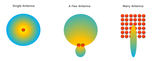
Figure 1. Beamforming concept
In the 5G New Radio (NR) initial access procedure, multiple synchronization signal blocks (SSBs) are sent in a burst set period, each SSB potentially in a different beam. The UE identifies every SSB in the burst set using the physical broadcast channel demodulation reference signal (PBCH DMRS) and the rest of the SSB index carried by the broadcast channel. After sweeping the beam, the UE then selects the best SSB and establishes the connection.
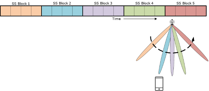
Figure 2. Beam sweeping concept
The UE uses the synchronization signals and system information to establish the connection on one beam. The random access response and system information, and the data and control channels help refine the beam.
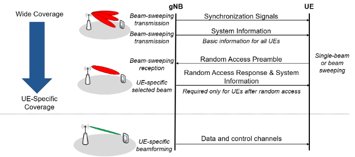
Figure 3. Beam refinement process
Beam refinement is a continuous process during the user session. It is needed after the initial access process because the UE might move, or the environment may have changed. You need to fight off reflections and diffractions.
Beam correspondence (BC) is another beamforming adaptation technique for the UE. A BC-enabled UE can select a suitable beam for uplink (UL) transmission based on downlink (DL) measurements with or without relying on UL beam sweeping. UEs that do not support BC require assistance from the base station.
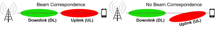
Figure 4. Beam correspondence concept
mmWave frequencies offer great potential for the wireless communications industry. Much more spectrum is available at these frequencies making usable bandwidth much higher than at lower frequencies. mmWave signals also bounce readily and give rise to local scattering, making it easy to steer them in certain directions and use multipath.
However, mmWave signals do not bend around corners and are easily blocked or attenuated, limiting their range. Path loss is also much greater. Lossy cables and greater device/system integration will drive testing to be mostly done over the air.
For more resources on 5G, visit Keysight’s 5G webpages at www.keysight.com/find/5G. You can also take our Intro to 5G course on Keysight University and test your knowledge of the 5G NR standards.